Tomography apparatus with an annular airflow channel with an air-diverting ventilation element

a technology of annular channel and ventilation element, which is applied in the field of tomography apparatus with annular channel, can solve the problems of high level of x-ray radiation, large challenge, and up to 99% of electrical energy used in generating x-rays, and achieve the effect of further reducing the acoustic emission of the operation of the air-cooled tomography apparatus

Inactive Publication Date: 2012-06-12
SIEMENS AG
View PDF8 Cites 3 Cited by
  • Summary
  • Abstract
  • Description
  • Claims
  • Application Information

AI Technical Summary

Benefits of technology

[0008]An object of the present invention is to provide a tomography apparatus wherein acoustic emissions during operation of an air cooled tomography apparatus are further reduced.
[0013]In order to reduce the acoustic emissions in identical air flows, or to increase the air flow while maintaining the same acoustic emissions, in accordance with the invention the air current through a special structure of the intake window, is modified so as to even out the flow profile at the output window. In this manner, selectively occurring peaks in the air flow speed are avoided and acoustic emissions are reduced. This is accomplished in that the intake window has a larger effective intake cross section at the sides.
[0015]By means of the larger intake cross-section in the sides, a larger portion of the air flow is drawn off at these areas than in the middle. As a result of the lower speed at which the air flows, by sizing the intake cross-section appropriately the air flow per unit of time transported to the output window can be kept nearly constant throughout the cross-section. In this manner a higher air flow and thereby a greater cooling effect is obtained.
[0016]In an embodiment of the invention, the tomography apparatus contains an annular channel through which the air current flows and in which the intake window of the ventilation element is located. An upper section of the intake window corresponding to an outer contour of the annular channel has a convex form. Thereby, the ventilation element can be easily integrated in the housing of the tomography apparatus and in a special case, can form a part of the housing.
[0017]The ventilation element furthermore contains a paddle, the front edge of which forms the lower section of the intake window. The ventilation element contains thereby individual structural groups, such that a simple fabrication and installment is possible.
[0018]Due to the modular construction of the ventilation element from individual structural groups it is possible to obtain various configurations with different intake cross-sections in a simple manner using the same components.

Problems solved by technology

A basic thermal problem for all computed tomography apparatuses is that up to 99% of the electrical energy used in generating X-rays is converted to heat.
This can be a particularly large challenge when, for sampling the region being examined, a high level of X-ray radiation is required.
The detector must also be cooled during the operation of the computed tomography apparatus, because with increasing heat the signal / noise ratio of the acquired values becomes worse, which results in a reduction of the image quality of reconstructed layered images.
Water cooled systems, however, are very expensive.

Method used


Image

  • Tomography apparatus with an annular airflow channel with an air-diverting ventilation element
  • Tomography apparatus with an annular airflow channel with an air-diverting ventilation element
  • Tomography apparatus with an annular airflow channel with an air-diverting ventilation element

Examples


Embodiment Construction

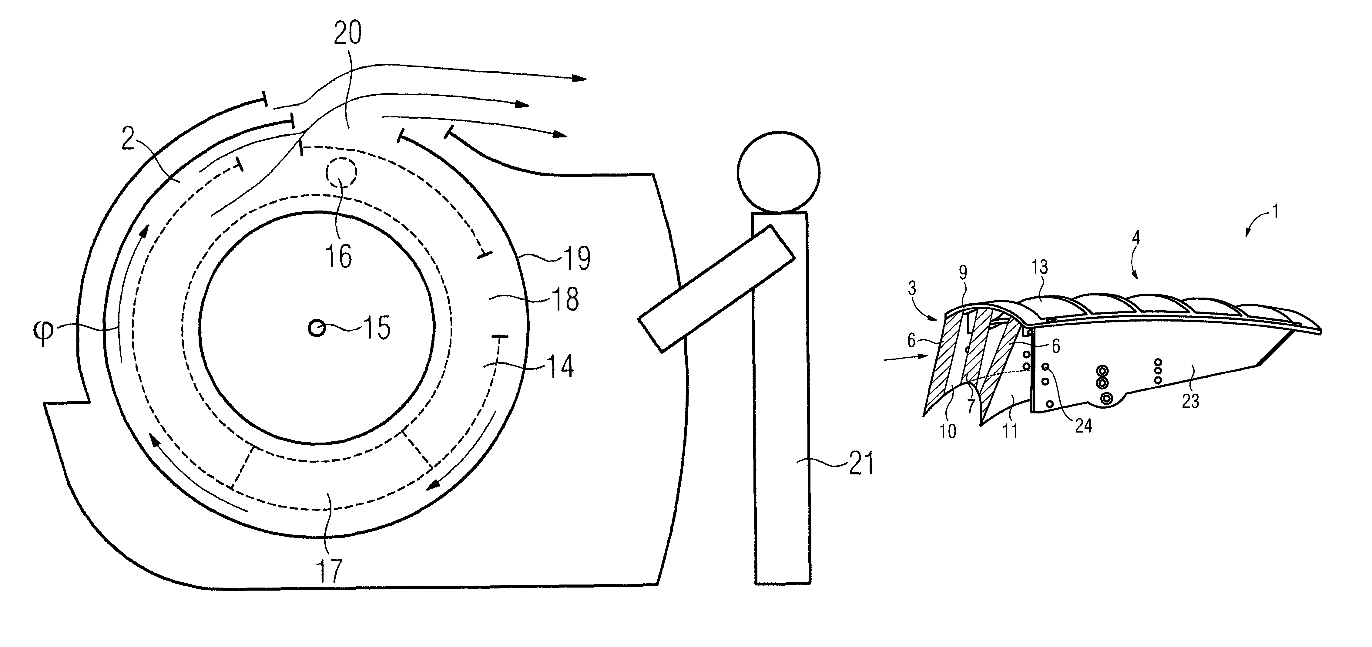
[0030]FIG. 1 shows a tomography apparatus, in this case a computed tomography apparatus, first without a ventilation element 1 shown in FIG. 2 and FIG. 3. Inside the apparatus there is a rotational frame 14 which can rotate on an axis 15 in the φ-direction shown. For cooling electronic components disposed on the rotational frame 14, such as, for example an X-ray tube 16 and a detector 17, the air is first directed toward the inside of the rotational frame 14. The directing of the air can be accomplished by means of a mount, not shown, with which the rotational frame 14 can also be tilted. In the rotational frame 14, a portion of the heat generated by the components is drawn off and subsequently directed through openings 18 to an annular channel 2 formed between a supporting frame 19 and the rotational frame 14. The annular channel 2 contains a gap 20 above the computer tomography apparatus such that the air current flowing through the annular channel 2 can be redirected through the ...


PUM


Abstract

A tomography apparatus has an annular channel and at least one ventilation element for the purpose of drawing off an air current flowing through the annular channel. The ventilation element contains an intake window that is located in the annular channel for the purpose of drawing off at least a portion of the air current. In order to obtain an even flow profile at an output window of the ventilation element, the intake window has a greater effective intake cross-section at both sides than at the middle. By such evening the flow profile at the output window, turbulence and air current interruptions of the air can be generally avoided, such that when operating the tomography apparatus, disrupting acoustic emissions may be reduced, or a higher air flow and thereby a greater cooling effect may be obtained.

Description

BACKGROUND OF THE INVENTION[0001]1. Field of the Invention[0002]The invention concerns a tomography apparatus with an annular channel and with at least one ventilation element for drawing off an air current flowing through said annular channel.[0003]2. Description of the Prior Art[0004]Using a tomography apparatus, such as a computed tomography apparatus for example, three-dimensional layered images are created of an area to be examined in a patient for the purposes of diagnosis or therapy. The basic structure of a computed tomography apparatus includes a gantry with a stationary supporting frame in which a rotational frame is mounted such that it can be rotated around an axis. Electronic components of a tomography data acquisition system are disposed on the rotational frame, such that through the rotation of the rotational frame with simultaneous constant forward motion of a patient located on a table along the system axis, projections are recorded from numerous different projectio...

Claims


Application Information

Patent Timeline
Patent Type & Authority Patents(United States)
IPC IPC(8): H05G1/02H01J35/02
CPCA61B6/032A61B6/4488
Inventor BUETTNER, THORSTENKRUG, RITASPECK, ANDREAS
Owner SIEMENS AG
Why Eureka
Try Eureka