AI technical title is built by Patsnap AI team. It summarizes the technical point description of the patent document.
a technology of pedicles and threads, applied in the field of threads, can solve the problems of locking pins, difficult for surgeons to grasp in the midst of surgery, lack of stabilized angular placement positions during installation, etc., and achieve the effect of lowering inventory costs
Active Publication Date: 2012-06-12
ORTHO INNOVATIONS
View PDF446 Cites 88 Cited by
Summary
Abstract
Description
Claims
Application Information
AI Technical Summary
This helps you quickly interpret patents by identifying the three key elements:
Problems solved by technology
Method used
Benefits of technology
Benefits of technology
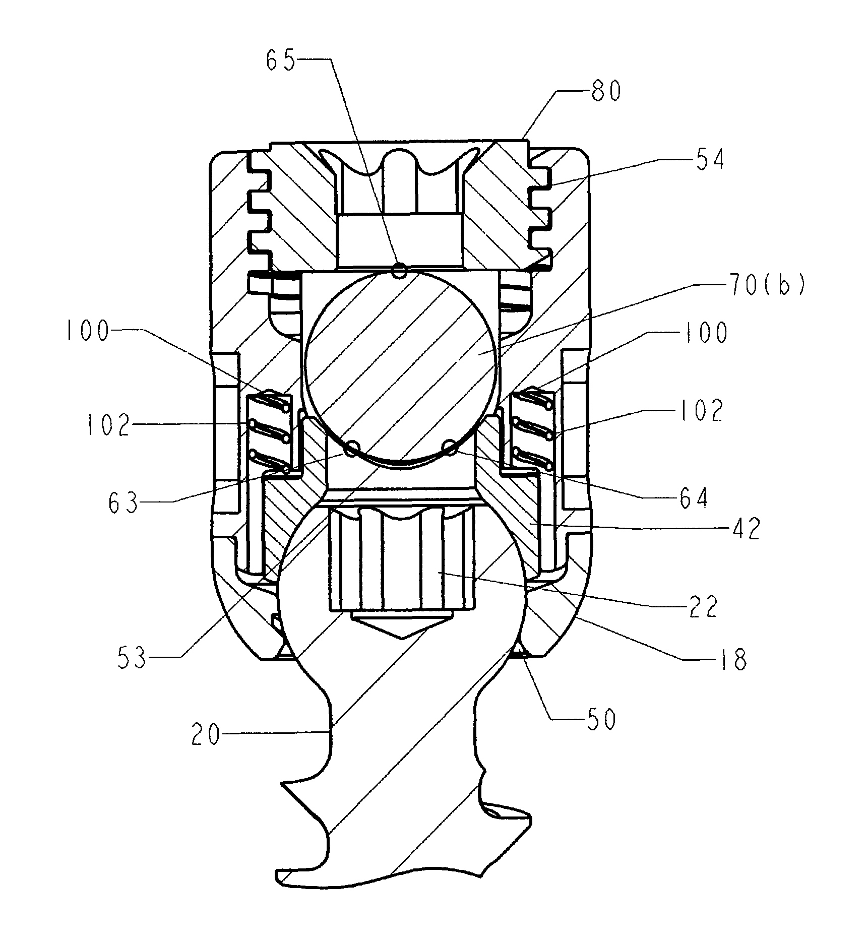
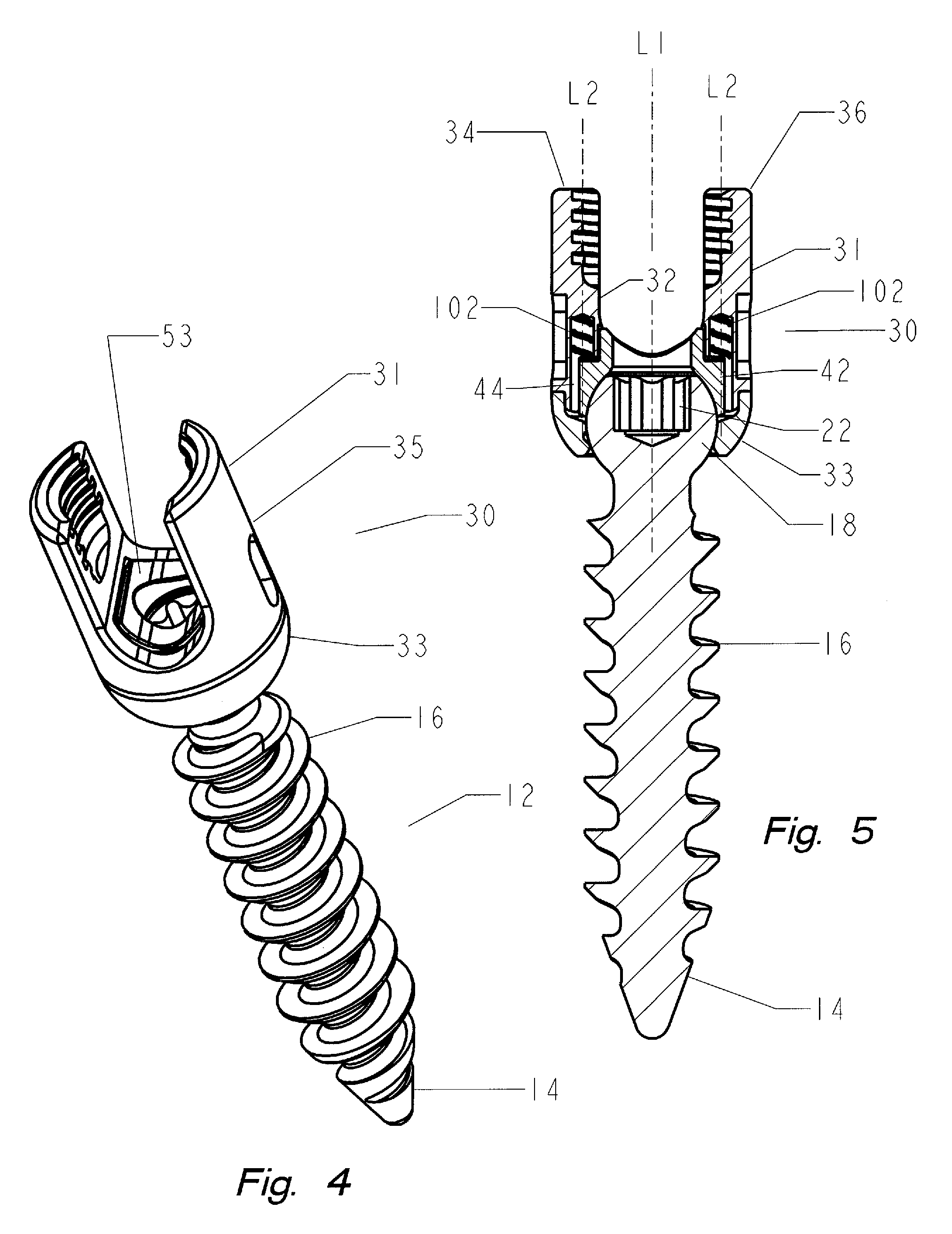
[0039]The present invention is a polyaxial pedicle screw system that permits the threads of a pedicle screw to pass thru a lower section of a connecting member during manufacturing. The pass thru design permits the manufacturer to use a range of different size shanks and threads while using a common connector member thereby lowering inventory costs and providing the surgeon with a similar shaped connector despite the type of pedicle screw employed. The system includes a means for applying tension to the pedicle screw anchoring member to assist in surgery.
[0040]The polyaxial bone screw has a threaded shank extending outwardly from a spherical ball for use in anchoring to the spine and a connector member that includes a socket constructed and arranged to accept the spherical ball. In the disclosed embodiment, the connector member is illustrated as a U-shaped connector member having a lower receptacle that operates as a socket for housing a retainer ring. The socket is receptive to the spherical ball which is inserted through the top of the connector during a manufacturing step. The retainer ring is spring loaded against a upper component of the connector member and engages the spherical ball so as to keep the U-shaped connector member in position during installation. The upper retainer ring is resiliently biased against an upper component of the connector member and engages the spherical ball so as to keep the U-shaped connector member in position during installation. A surgeon can easily move the connector member into a preferred position and the resilient biasing component will keep sufficient force on the upper retainer ring so as to maintain the connector in a selected position relative to the spherical connector. This facilitates the installation of the rod as the U-shaped connector not only can be rotated into a position for proper placement of the connecting rod but the proper angle of the saddle can also maintained while allowing the surgeon to align additional screws for ease of rod placement. In addition, by maintaining the pre positioning of the connector members the surgeon will be able to pre position and bend the rod as needed to align for any number of anchoring screws.
[0043]Accordingly, it is an objective of the present invention to teach the use of a polyaxial pedicle screw system for posterior fixation having a common connector for use with different sized shanks and thread types, which lowers inventory requirements and provides the surgeon with a uniform connector.
[0044]It is another objective of the present invention to teach the use of a polyaxial pedicle screw having a biasing member to apply a force between the anchoring member and the connector member, the force facilitates installation by maintaining the connector component in an angular placement position as desired by the surgeon. A polyaxial ball and socket system that permits component adjustment during installation thereby enabling satisfactory correction of a wide variety of spinal deformities.
[0045]It is another objective of the present invention to teach the use of a polyaxial bone screw assembly having a thicker connector even when oversized anchoring screws are employed by use of a thread thru design of a lower connector, the upper connector need not be threaded providing a greater safety factor when a set screw fastener is employed by avoiding splaying.
[0049]It is yet another objective of the present invention to provide a simple spinal fixation system having only a few components for use in assembly and limiting component parts needed during assembly by use of a common connector.
Problems solved by technology
However, one of the problems with a polyaxial pedicle screw is the lack of a stabilized angular placement position during installation.
Once a polyaxial pedicle screw is inserted into the bone, the connector component portion has yet to receive a connecting rod leaving the connector assembly to flop over making it difficult for the Surgeon to grasp while in the midst of surgery.
This problem is compounded by the need to align multiple component heads for receipt of a connecting rod.
Another problem with the prior art is the inability to use various size anchoring screw in combination with a common saddle larger saddle, both of which leads to assembly integrity over a large range of installation considerations.
The disclosed structure would not prevent relative movement between a fastener and a housing and would not hold a longitudinal axis of the fastener in any one of a plurality of desired angular positions relative to a longitudinal of a passage in the housing when a rod, longitudinal member, is disengaged from a spacer.
The patent does not teach an arrangement where a spacer necessarily engages a fastener when a rod, longitudinal member, is so disengaged.
A problem with the screw is the need for the locking pin and the inability of the base screw to accommodate a threaded extension bolt.
Method used
Image
Click on the blue label to locate the original text in one second.
Reading with bidirectional positioning of images and text.
Examples
Embodiment Construction
[0076]While the present invention is susceptible of embodiment in various forms, there is shown in the drawings and will hereinafter be described a presently preferred embodiment with the understanding that the present disclosure is to be considered an exemplification of the invention and is not intended to limit the invention to the specific embodiments illustrated.
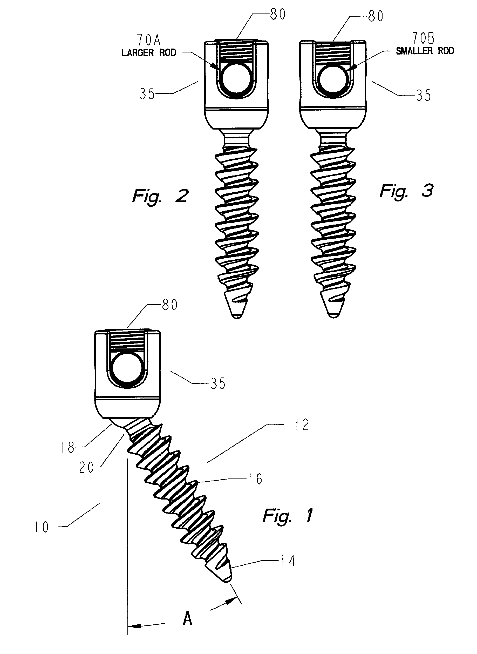
[0077]Referring generally to the Figures, disclosed is an exemplary embodiment of the thread thru polyaxial pedicle screw system for use in a spinal fixation system. The thread-thru pedicle screw system (10) is based on an anchoring member formed from a bone screw (12) including a shank (14) with at least one helical thread (16) formed along the length thereof. It is important to note that the proportions of the bone screw depicted are for illustrative purposes only and variations in the length of the shank, diameter of the screw, thread pitch, thread length, number of thread leads, shank induced compression and the like...
PUM
Abstract
A thread-thru polyaxial pedicle screw fastening system. The fastening system consists of an anchoring bone screw having threads on one end for use in anchoring to the screw to the spine and a spherical connector on the other end operating as a pivot point about which a U-shaped connecting assembly moves in a polyaxial fashion. The U-shaped connecting assembly, for receipt of a spinal connecting rod, has a biased retainer ring for maintaining a positive tension between the connecting assembly and the anchored screw. The system allows for an improved manufacturing step wherein the threaded shank of a bone screws can be passed through a lower portion of the connecting assembly allowing a variety of bone screw sizes to be used with a common sized connector. A resilient component positioned between the upper retainer ring and the connecting assembly permits relative predetermined placement and retention of the spherical connector relative to the connector assembly due to the force generated by the resilient component and frictional engagement between the surfaces of spherical connector, the retainer ring and the connector assembly. The polyaxial ball and socket can be locked into a fixed position.
Description
CROSS REFERENCE TO RELATED APPLICATIONS[0001]This application is a continuation in part of U.S. patent application Ser. No. 12 / 540,398 entitled Thread-Thru Polyaxial Pedicle Screw System, filed Aug. 13, 2009, now U.S. Pat. No. 7,942,909, which in turn is related to U.S. patent application Ser. No. 12 / 355,145, filed Jan. 16, 2009, which claims the benefit of the filing date of U.S. Provisional Patent Application No. 61 / 114,515, filed on Nov. 14, 2008; and U.S. patent application Ser. No. 11 / 749,615, filed May 16, 2007, now U.S. Pat. No. 7,942,910,the contents of these applications are herein incorporated by reference.FIELD OF THE INVENTION[0002]This invention is directed to the field of pedicle screws, and in particular, to a thread-thru polyaxial pedicle screw system adapted for use as a spinal implant.BACKGROUND OF THE INVENTION[0003]The use of pedicle screw fasteners is well known for their use with spinal fixation systems. In the field of spinal pathologies, spinal fixation syste...
Claims
Application Information
Patent Timeline
Application Date:The date an application was filed.
Publication Date:The date a patent or application was officially published.
First Publication Date:The earliest publication date of a patent with the same application number.
Issue Date:Publication date of the patent grant document.
PCT Entry Date:The Entry date of PCT National Phase.
Estimated Expiry Date:The statutory expiry date of a patent right according to the Patent Law, and it is the longest term of protection that the patent right can achieve without the termination of the patent right due to other reasons(Term extension factor has been taken into account ).
Invalid Date:Actual expiry date is based on effective date or publication date of legal transaction data of invalid patent.

