Portable electronic device with chip card ejecting mechanism

a technology of electronic devices and chip cards, applied in the direction of coupling device connections, electrical apparatus casings/cabinets/drawers, instruments, etc., can solve the problem of difficulty for users to grasp

Inactive Publication Date: 2012-06-12
SHENZHEN FUTAIHONG PRECISION IND CO LTD +1
View PDF11 Cites 11 Cited by
  • Summary
  • Abstract
  • Description
  • Claims
  • Application Information

AI Technical Summary

Benefits of technology

[0005]Typically, chip card holders define a receiving groove for receiving the chip card. The chip card is partly received in the receiving groove to electronically connect to a circuit of the device employing the chip card, and partly exposed so that it may be gripped for removal. However, the exposed part of the chip card is usually small and therefore difficult for a user to grasp in removing the chip card from the holder.

Problems solved by technology

However, the exposed part of the chip card is usually small and therefore difficult for a user to grasp in removing the chip card from the holder.

Method used


Image

  • Portable electronic device with chip card ejecting mechanism
  • Portable electronic device with chip card ejecting mechanism
  • Portable electronic device with chip card ejecting mechanism

Examples


Embodiment Construction

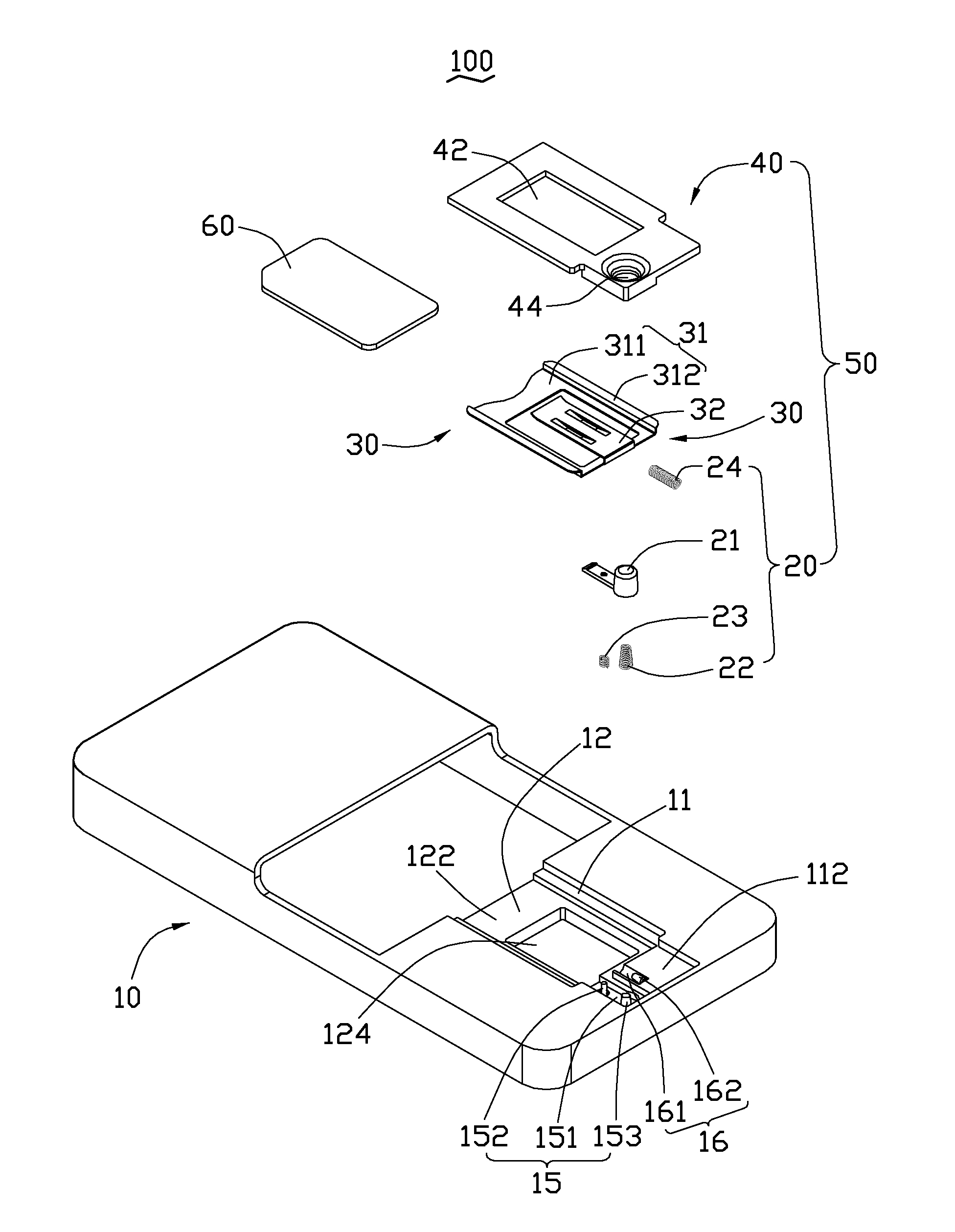
[0015]Referring to FIG. 1, an embodiment of a chip card ejecting mechanism 50 can be used on a portable electronic device 100, such as a cellular phone or any electronic device where a chip card is desirable. The portable electronic device 100 includes a housing 10 and a chip card ejecting mechanism 50 mounted to the housing 10. The chip card ejecting mechanism 50 is configured to mount the chip card 60 to the housing 10.

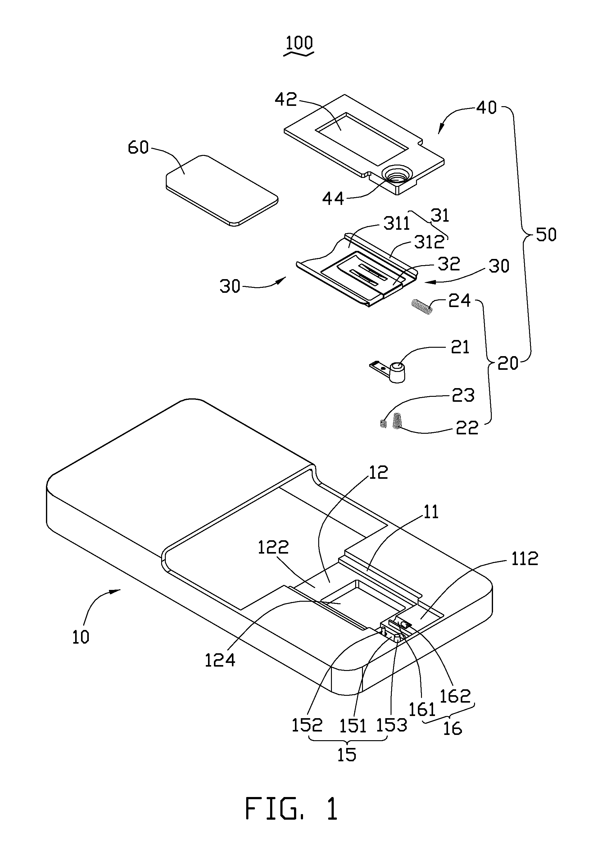
[0016]The chip card ejecting mechanism 50 includes a controlling module 20, a holder 30 and a cover 40. The controlling module 20 includes a button 21, two restoring elements, such as two elastic members 22, 23 and an ejecting element, such as an elastic member 24. In this exemplary embodiment, the elastic members 22, 24 are both cylindrical springs, the elastic member 23 is a tapered spring. Referring to FIG. 2, the button 21 has an operating portion 211 and a latching portion 212. The operating portion 211 may be a hollow cylinder that defines a tapered chamber 21...


PUM


Abstract

A portable electronic device comprises a housing and a chip card ejecting mechanism. The housing has a mounting portion defined therein. The ejecting mechanism includes a holder and a controlling module. The holder is slidably accommodated in the mounting portion of the housing. The controlling module includes a button and an ejecting element. The button releasably secures with the holder in the mounting portion. The ejecting element resistes against the holder to provide an elastic force for driving the holder slid. When the button is pressed, the holder is released and the ejecting element ejects the holder outwardly from the mounted portion of the housing.

Description

BACKGROUND[0001]1. Technical Field[0002]The present disclosure relates to portable electronic devices, and particularly to portable electronic devices with chip card ejecting mechanisms.[0003]2. Description of Related Art[0004]Commonly, portable electronic devices such as mobile phones include a chip card holder for holding the chip card therein.[0005]Typically, chip card holders define a receiving groove for receiving the chip card. The chip card is partly received in the receiving groove to electronically connect to a circuit of the device employing the chip card, and partly exposed so that it may be gripped for removal. However, the exposed part of the chip card is usually small and therefore difficult for a user to grasp in removing the chip card from the holder.[0006]Therefore, there is room for improvement within the art.BRIEF DESCRIPTION OF THE DRAWINGS[0007]Many aspects of the embodiments can be better understood with references to the following drawings. The components in t...

Claims


Application Information

Patent Timeline
Patent Type & Authority Patents(United States)
IPC IPC(8): G06F1/16
CPCH04B1/3816H04M1/026H01R13/635H04M2250/14G06K7/003
Inventor LIANG, HUA-XIANGTU, HSIAO-HUAWANG, JUN
Owner SHENZHEN FUTAIHONG PRECISION IND CO LTD
Why Eureka
Try Eureka