Low profile light

Active Publication Date: 2012-06-19
LIGHTING SCI GROUP
View PDF4 Cites 165 Cited by
  • Summary
  • Abstract
  • Description
  • Claims
  • Application Information

AI Technical Summary

Problems solved by technology

However, such configurations typically result in unique designs for each type and size of fixture.

Method used


Image

  • Low profile light
  • Low profile light
  • Low profile light

Examples


Embodiment Construction

[0032]Although the following detailed description contains many specifics for the purposes of illustration, anyone of ordinary skill in the art will appreciate that many variations and alterations to the following details are within the scope of the invention. Accordingly, the following preferred embodiments of the invention are set forth without any loss of generality to, and without imposing limitations upon, the claimed invention.

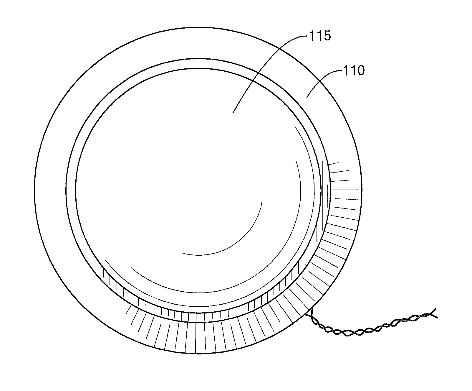
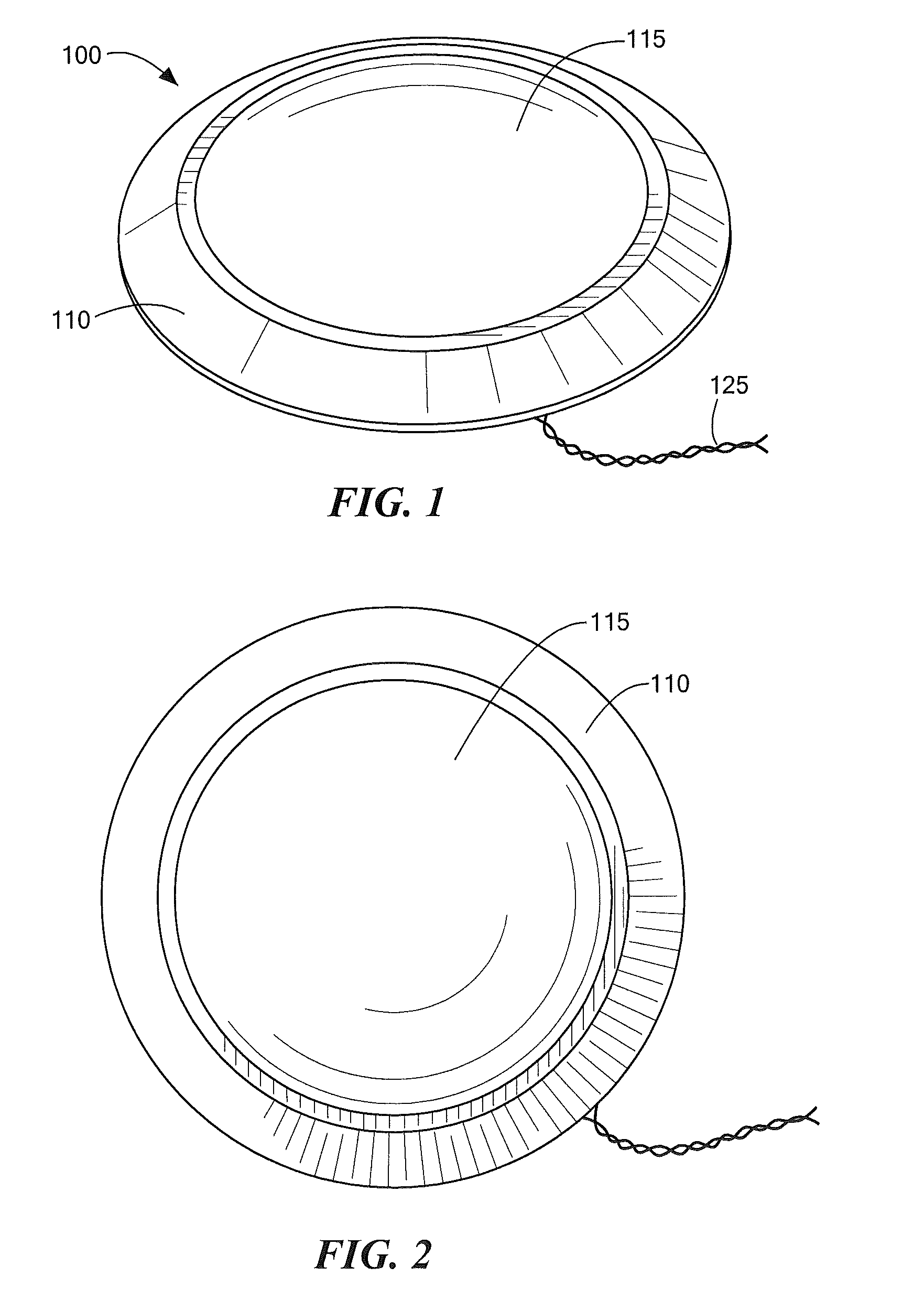
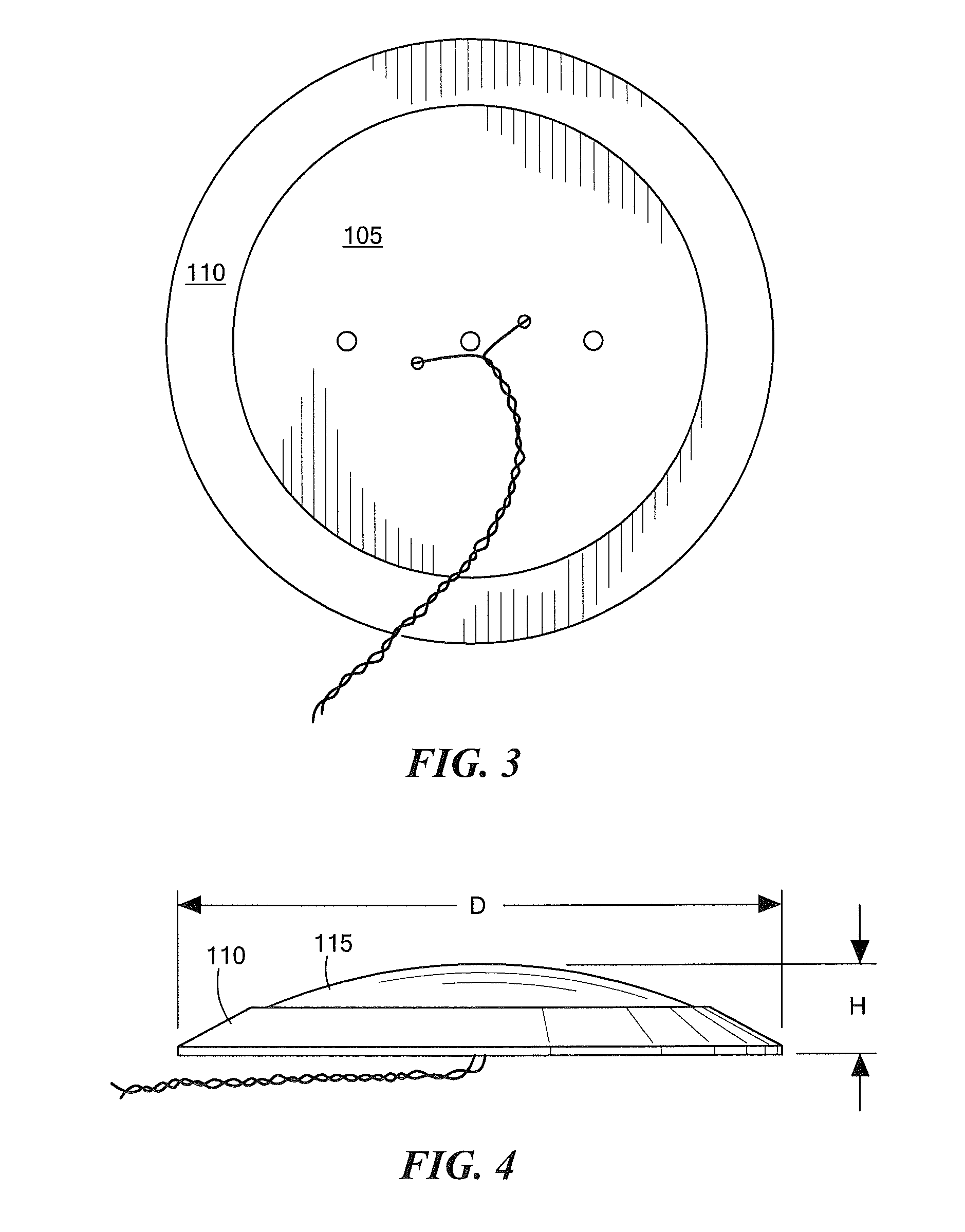
[0033]An embodiment of the invention, as shown and described by the various figures and accompanying text, provides a low profile downlight, more generally referred to as a luminaire, having an LED light source disposed on a heat spreader, which in turn is thermally coupled to a heat sink that also serves as the trim plate of the luminaire. The luminaire is configured and dimensioned for retrofit installation on standard can-type light fixtures used for recessed ceiling lighting, and on standard ceiling or wall junction boxes (J-boxes) used for ceiling o...


PUM


Abstract

A luminaire includes a heat spreader and a heat sink thermally coupled to and disposed diametrically outboard of the heat spreader, an outer optic securely retained relative to at least one of the heat spreader and the heat sink, and a light source disposed in thermal communication with the heat spreader, the light source having a plurality of light emitting diodes (LEDs). The heat spreader, the heat sink and the outer optic, in combination, have an overall height H and an overall outside dimension D such that the ratio of H / D is equal to or less than 0.25. The combination defined by the heat spreader, the heat sink and the outer optic, is so dimensioned as to: cover an opening defined by a nominally sized four-inch can light fixture; and, cover an opening defined by a nominally sized four-inch electrical junction box.

Description

CROSS REFERENCE TO RELATED APPLICATIONS[0001]This application claims the benefit of U.S. Provisional Application Ser. No. 61 / 248,665, filed Oct. 5, 2009, which is incorporated herein by reference in its entirety.BACKGROUND OF THE INVENTION[0002]The present disclosure relates generally to lighting, particularly to low profile lighting, and more particularly to low profile downlighting for retrofit applications.[0003]Light fixtures come in many shapes and sizes, with some being configured for new work installations while others are configured for old work installations. New work installations are not limited to as many constraints as old work installations, which must take into account the type of electrical fixture / enclosure or junction box existing behind a ceiling or wall panel material. With recessed ceiling lighting, sheet metal can-type light fixtures are typically used, while surface-mounted ceiling and wall lighting typically use metal or plastic junction boxes of a variety of...

Claims


Application Information

Patent Timeline
Patent Type & Authority Patents(United States)
IPC IPC(8): F21V1/00F21V29/00
CPCF21S8/026F21S8/04F21V29/004F21V29/2212F21V21/02F21V21/04F21Y2101/02F21Y2115/10F21V29/773F21V29/70
Inventor MAXIK, FREDRIC S.REYNOLDS, RAYMOND A.WIDJAJA, ADDY S.BOOMGAARDEN, MARK PENLEYSOLER, ROBERT RAFAELSCHELLACK, JAMES L.
Owner LIGHTING SCI GROUP
Why Eureka
Try Eureka