Follicular extraction punch and method

a technology of follicular and ovaries, applied in the field of surgical instruments, to achieve the effect of facilitating fi

Active Publication Date: 2012-06-19
COLE JOHN P
View PDF65 Cites 37 Cited by
  • Summary
  • Abstract
  • Description
  • Claims
  • Application Information

AI Technical Summary

Problems solved by technology

However, of all the prior art, none has thus far provided an instrument through the use of which the precise depth of incision is repeatedly and precisely controlled to result in the vast majority of follicles extracted to continue to furnish hair at the new site to which they are transplanted.

Method used


Image

  • Follicular extraction punch and method
  • Follicular extraction punch and method
  • Follicular extraction punch and method

Examples


Embodiment Construction

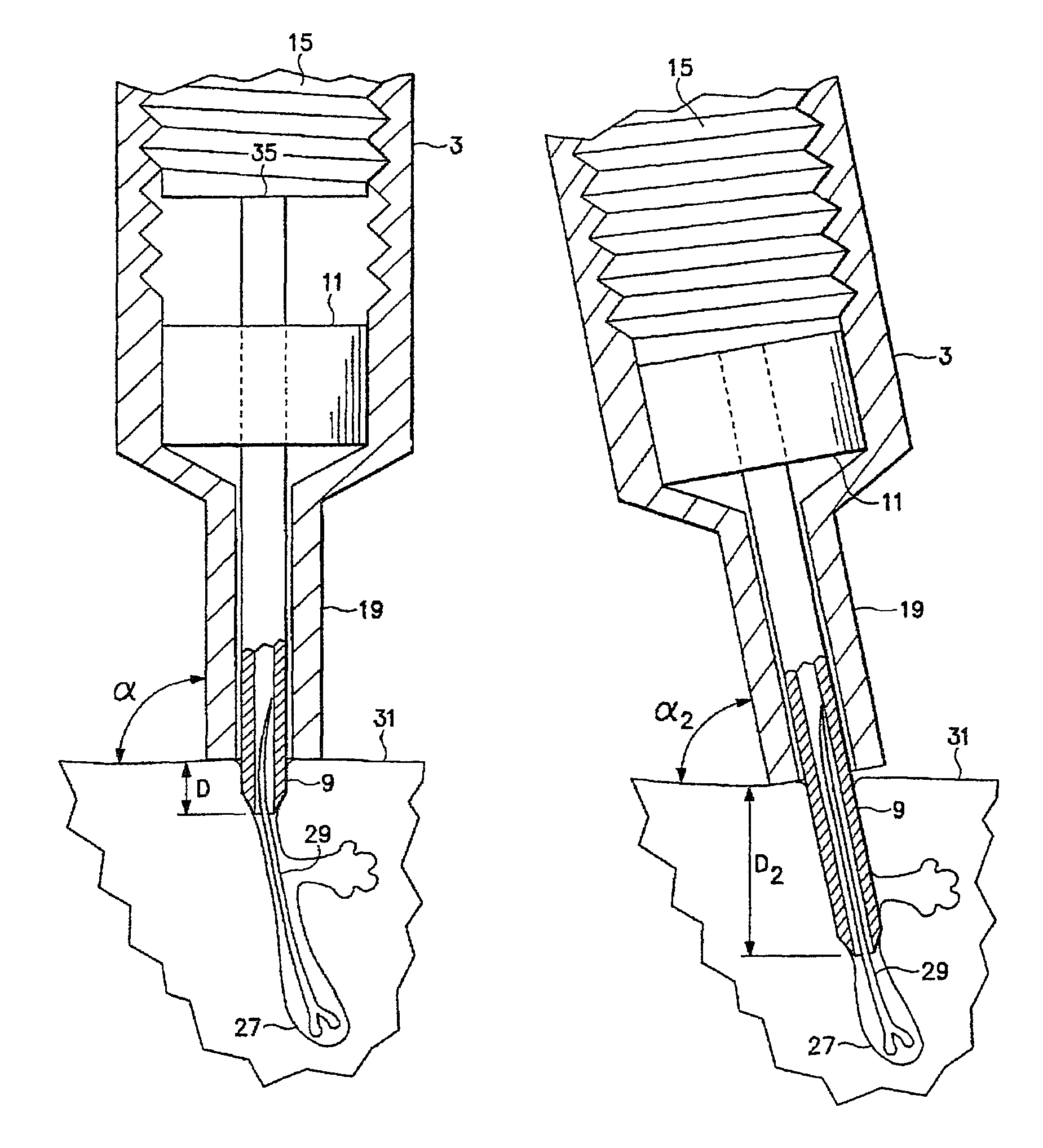
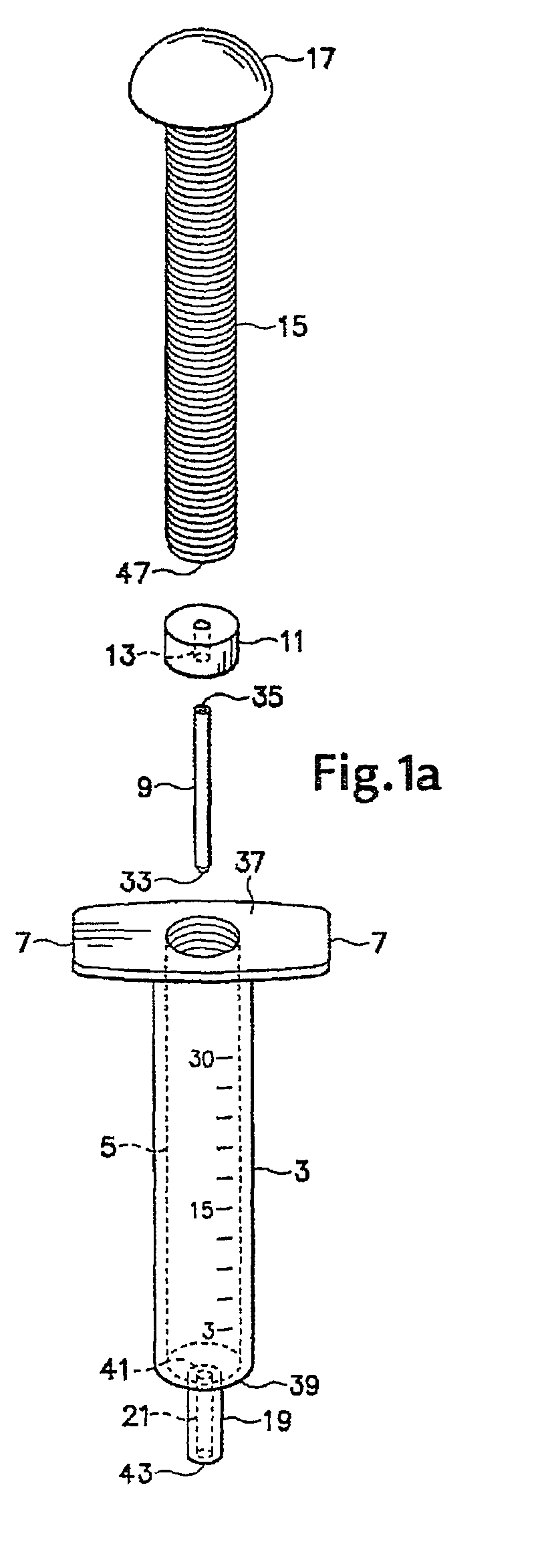
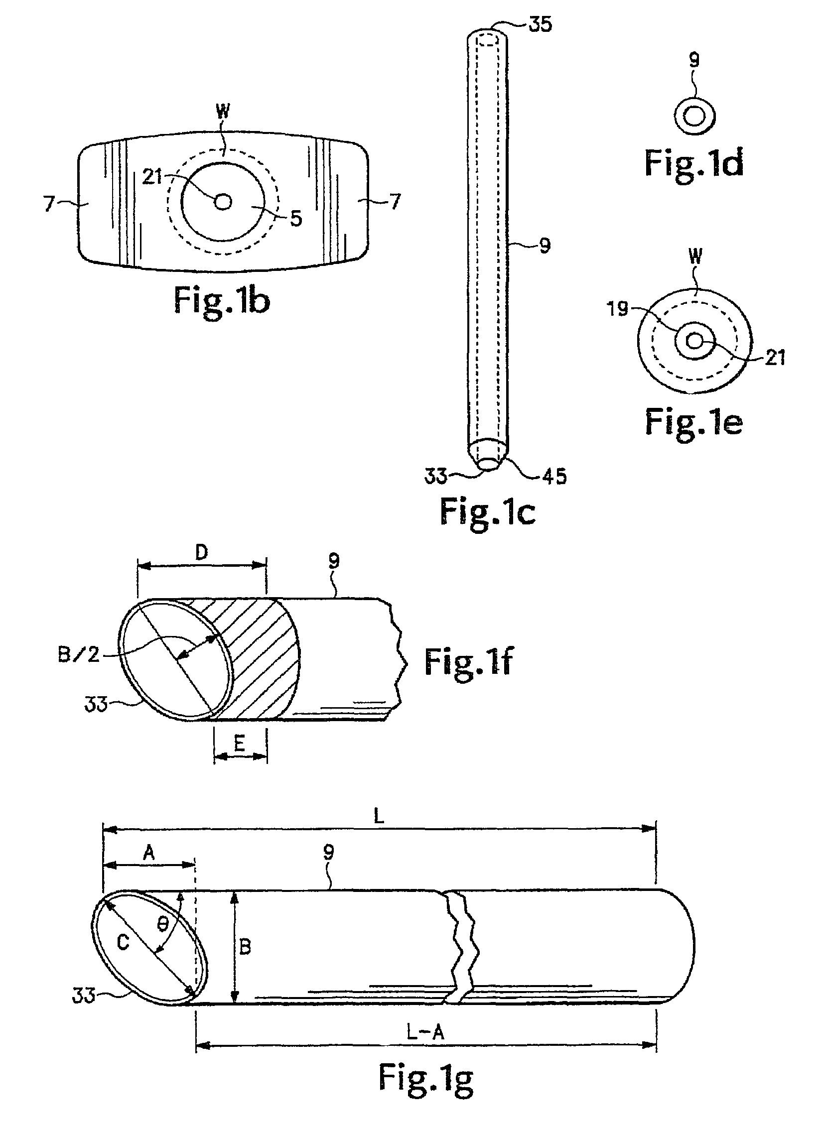
[0022]Referring to the drawings and initially to FIG. 1a there is shown an exploded perspective view of the various components of a tool according to the invention, including the main body portion 3, tubular punch means 9, stabilizer means 11, and adjusting screw 15. The main body portion 3 in a preferred form of the invention is a construct which is substantially cylindrically shaped, having an open first end portion 37 and a second end portion 39. The main body portion 3 further includes a bore 5 centrally disposed therewithin along its longest length dimension, which bore in one preferred form of the invention extends from the first end portion 37 to the second end portion 39. The walls of the main body portion 3 at the second end portion 39 are tapered inwards towards the axis of the bore 5, and coextensively intersect a nipple end portion 19, which nipple end portion 19 is substantially cylindrically shaped and includes a first end portion 41 and a tip portion 43. Such an arran...


PUM


Abstract

A method and apparatus disclosed herein may incise into a patient's skin to a precise depth and at a specific angle with respect to a surface of the patient's to extract individual follicular groups or individual follicular units. An apparatus as disclosed herein may precisely limit a depth of an incision, and perform a circular incision around a hair, follicular unit, or follicular cluster without damaging any hair shafts.

Description

CROSS-REFERENCE TO RELATED APPLICATION[0001]The present application is a continuation-in-part of U.S. application Ser. No. 10 / 795,835 filed Mar. 9, 2004 titled, “Follicular Extraction Device and Method” by John P. Cole, now U.S. Pat. No. 7,172,604.TECHNICAL FIELD[0002]This invention relates generally to surgical instruments useful for extracting live hair follicles from mammalian subjects for transplantation on other parts of the body of such subjects. More specifically, the invention provides a surgical instrument useful for extracting live hair follicles from human skin for transplantation to other portions of the skin, such as the scalp. An instrument according to the invention precisely controls the depth to which an incision is made during the follicular extraction process.BACKGROUND[0003]The prior art contains numerous examples of instruments useful for extracting live hair follicles from the skin of human subjects, and methods associated with the use thereof. U.S. Pat. No. 4,...

Claims


Application Information

Patent Timeline
Patent Type & Authority Patents(United States)
IPC IPC(8): A61B17/50A61B17/00A61B17/32A61B17/322A61B17/34A61B19/00
CPCA61B17/32053A61B17/3468A61B17/322A61B17/3403A61B17/3496A61B2017/00752A61B2017/00902A61B2017/00969A61B2017/3492A61B2019/306A61B2019/462A61B2090/036A61B2090/062
Inventor COLE, JOHN P.
Owner COLE JOHN P
Why Eureka
Try Eureka