Pulse arc welding method

a technology of arc welding and arc welding, which is applied in the direction of arc welding apparatus, welding apparatus, manufacturing tools, etc., can solve the problems of unstable arc, reset the unit, and inability to work normally, and achieve the effect of stable arc condition

Active Publication Date: 2012-06-19
DAIHEN CORP
View PDF12 Cites 31 Cited by
  • Summary
  • Abstract
  • Description
  • Claims
  • Application Information

AI Technical Summary

Benefits of technology

[0020]It is therefore an object of the present invention to provide a pulse arc welding method which ensures a stable arc condition, even when the shielding gas mixture ratio and the tip-base distance are changed.

Problems solved by technology

A tip-base distance Lw which is unduly smaller or greater than the reference value will cause unstable welding.
Thus, it is often unnecessary to reset the unit pulse condition even when the argon gas ratio is changed to increase.
On the other hand, when the argon gas ratio in the shielding gas is changed to decrease, the arc becomes unstable because the droplet transfer will not readily occur, as described below with reference to FIG. 13.
Accordingly, a number of undercuts will be produced, and the bead appearance will deteriorate.
The above-described problem arises when the shielding gas mixture ratio varies.
Another problem comes up when the tip-base distance is changed from the reference value.
However, the deviation is over ±3 mm (for example, about ±5 mm), the welding condition will unduly deteriorate.

Method used


Image

  • Pulse arc welding method
  • Pulse arc welding method
  • Pulse arc welding method

Examples


first embodiment

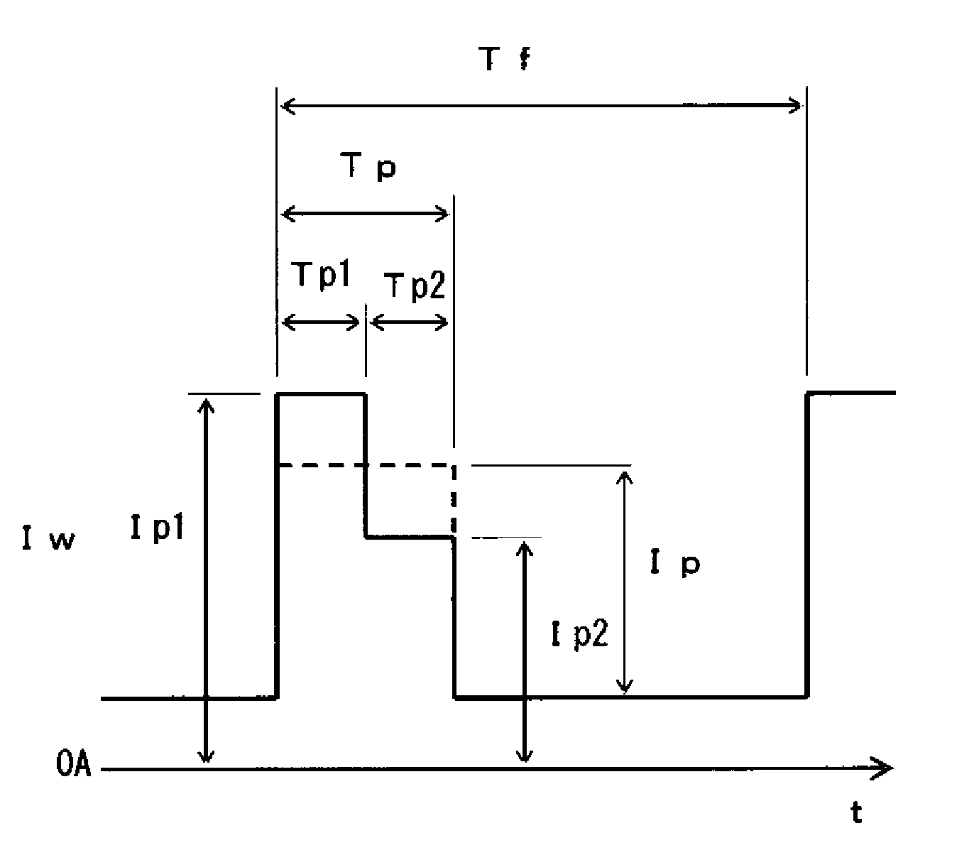
[0037]FIG. 1 shows the waveform of a welding current Iw in a pulse arc welding method according to the present invention. As shown in the figure, a peak time Tp is made up of two consecutive periods of times, i.e. a first peak time Tp1 and a second peak time Tp2 that follows the first peak time Tp1 without any interruptions. During the first peak time Tp1, a first peak current Ip1 is applied to flow through a welding wire and a base metal, while during the second peak time Tp2, a second peak current Ip2 is applied, which is smaller in value than the first peak current Ip1. Thus, the peak time current as a whole has a step-like form, with the right-hand part reduced below the left-hand part.

[0038]As indicated in broken lines in FIG. 1, the conventional peak time current is fixed to have a constant value Ip. The first peak current Ip1 is greater than the constant value Ip. The application of the first peak current Ip1 in the first peak time Tp1 contributes to positioning an arc anode ...

second embodiment

[0058]the present invention will now be described below.

[0059]According to the second embodiment, the welding current Iw (FIG. 1) described above in the first embodiment is also applied, and in addition, a control is performed for stabilizing the welding condition even when the tip-base distance becomes greater than the reference value.

[0060]Specifically, when the tip-base distance becomes greater than the reference value, the arc length control is conducted so as to maintain the arc length, and for this purpose the wire extension is made greater. Heat input for droplet formation comes from the arc heat and Joule heat at the extending portion of the wire. Accordingly, a greater wire extension leads to increased Joule heat and increased heat input for droplet formation, and excessive heat input may hinder a proper droplet transfer. This problem becomes more significant as the tip-base distance becomes greater. In order to overcome this problem, according to the second embodiment, the...

third embodiment

[0070]the present invention will now be described below.

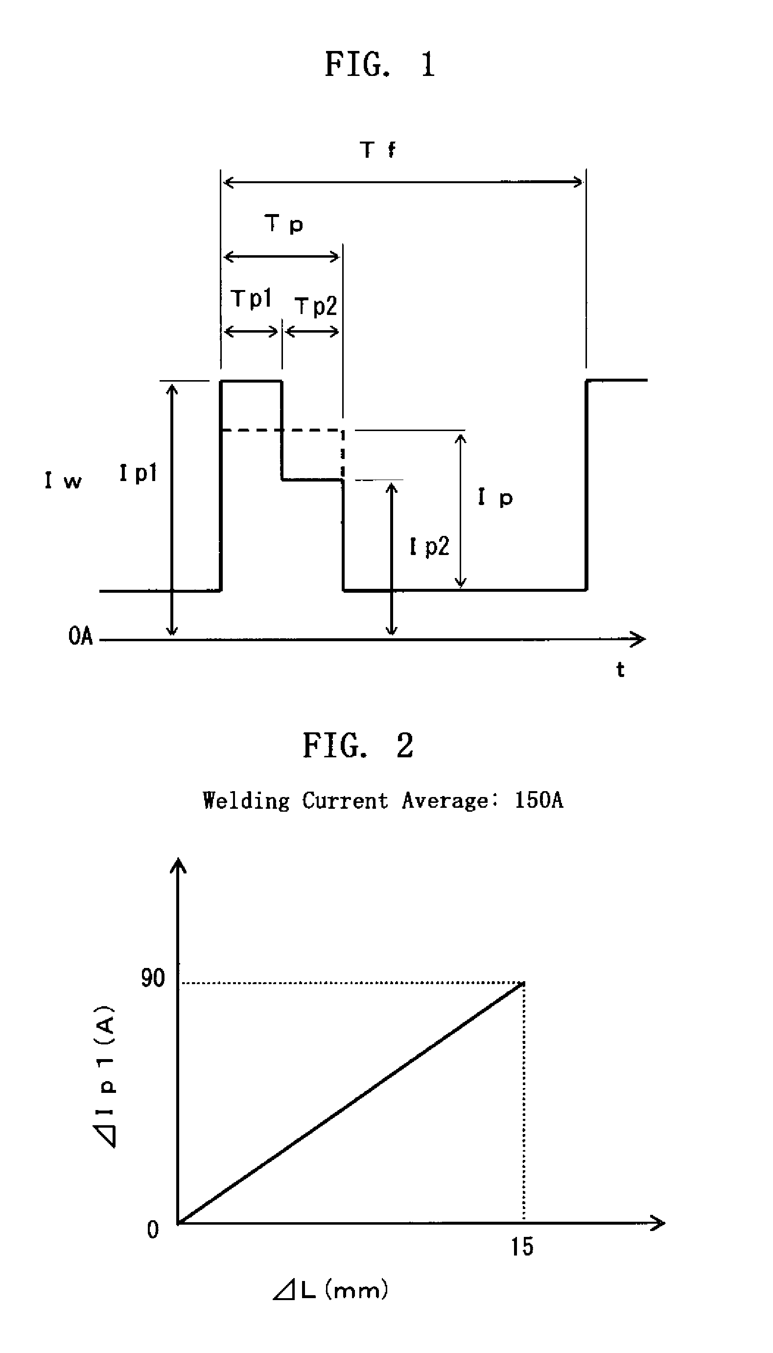
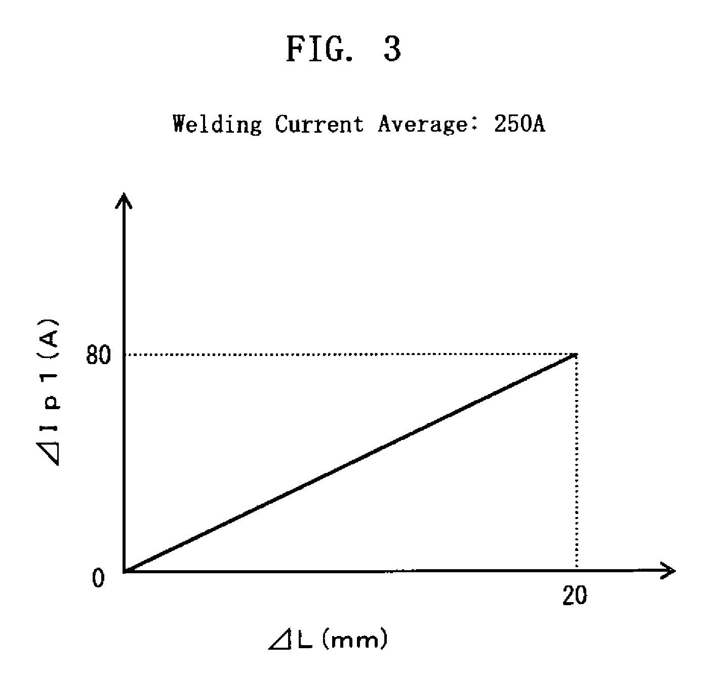
[0071]According to the third embodiment, the distance difference signal ΔL described above for the first and the second embodiments is calculated from the welding current average setting signal Iar and the welding current average.

[0072]FIG. 8 is a block diagram of a welding power source for implementing the pulse arc welding method according to the third embodiment. In FIG. 8, those blocks which are identical or similar to those described above with reference to FIG. 4 and FIG. 7 are indicated by the same reference symbols. FIG. 8 is essentially the same as FIG. 7, differing in that the interface circuit IF is replaced by a second interface circuit IF2 drawn in broken lines, the distance difference calculation circuit DL is replaced by a second the distance difference calculation circuit DL2, and a welding current average detection circuit IAV is added.

[0073]The second interface circuit IF2 receives the welding condition signal...


PUM

PropertyMeasurementUnit
distance Lwaaaaaaaaaa
diameteraaaaaaaaaa
currentaaaaaaaaaa

Abstract

A pulse arc welding method is provided for performing welding by causing welding current to flow through a welding wire and a base metal via a power supply tip. The welding current has a pulse cycle made up of a first peak time, a second peak time and a base time. A first peak current is applied during the first peak time, a second peak current, smaller than the first peak current, is applied during the second peak time, and a base current is applied during the base time. When a tip-base distance between an end of the power supply tip and the base metal is smaller or greater than a reference value, the first peak current is increased or decreased in accordance with the difference between the reference value and the tip-base distance.

Description

BACKGROUND OF THE INVENTION[0001]1. Field of the Invention[0002]The present invention generally relates to a pulse arc welding method. In particular, the present invention relates to a pulse arc welding method that enables stable welding, even when the mixture ratio of shielding gas varies and the distance between the power supply tip and the base metal changes.[0003]2. Description of the Related Art[0004]FIG. 9 shows the configuration of a typical consumable electrode arc welding system utilizing a welding robot. The welding system includes components described below.[0005]The conventional welding system is provided with a welding power source PS. As seen from the figure, the power source PS receives a welding condition signal Wc as an input from a robot controller RC, and then outputs welding voltage Vw and welding current Iw for arc generation. The power source PS also outputs a feed control signal Fc to a wire feeding motor WM for performing controlled feeding of a welding wire ...

Claims


Application Information

Patent Timeline
Patent Type & Authority Patents(United States)
IPC IPC(8): B23K9/10
CPCB23K9/173B23K9/092
Inventor UEDA, YUJI
Owner DAIHEN CORP
Why Eureka
Try Eureka