An igbt drive circuit with power-on protection

A driving circuit and driver technology, applied in emergency protection circuit devices, electrical components, electronic switches, etc., can solve problems such as affecting IGBT switching, burning IGBT, IGBT conduction, etc., to achieve complete safety protection, reliable operation, and stable control. Effect

Inactive Publication Date: 2011-11-30
WUHAN UNIV OF TECH +1
View PDF4 Cites 28 Cited by
  • Summary
  • Abstract
  • Description
  • Claims
  • Application Information

AI Technical Summary

Problems solved by technology

The general-purpose I / O pin of the general micro-control module is in the internal pull-up or high-impedance state. When power-on reset, crash or strong external high-frequency radiation, the output impact level of the drive module will affect the IGBT switch.
[0008] (2) There is no protection between the drive signal output by the micro-control chip and the drive module
Many drive circuits on the market directly input the PWM signal output by the micro-control module to the drive module. First, the signal output by the micro-control module is supplied to the drive module and there is a problem of insufficient drive capability. Secondly, when uncertain factors cause the output of the micro-control module to If the PWM signal is always high, it will cause the IGBT to be turned on until the IGBT is burned
[0009] (3) At present, the existing drive circuit protection scheme adopts protection when over-current is detected, and does not consider that the over-current is a false protection signal caused by external interference, resulting in false protection of IGBT

Method used


Image

  • An igbt drive circuit with power-on protection
  • An igbt drive circuit with power-on protection
  • An igbt drive circuit with power-on protection

Examples


Embodiment Construction

[0023] The present invention will be further described below in conjunction with the accompanying drawings and embodiments, but these embodiments should not be construed as limiting the present invention.

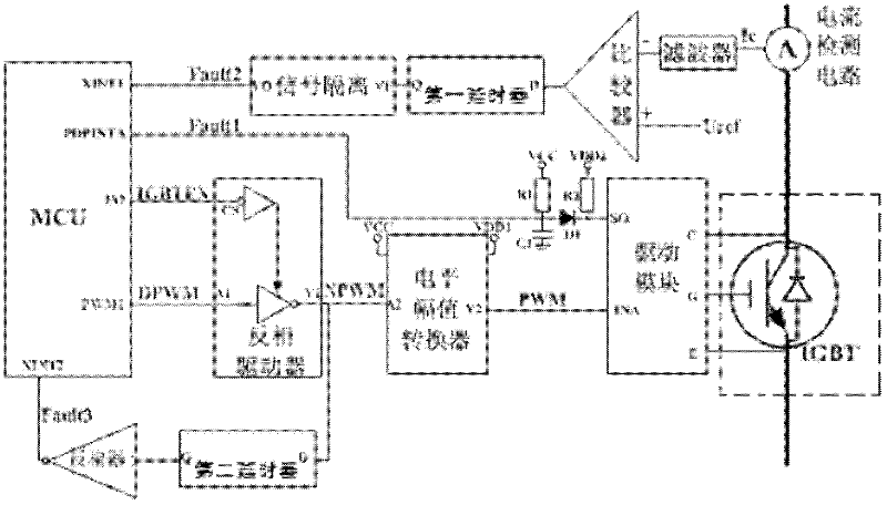
[0024] The schematic diagram of the circuit of the present invention is as figure 1 As shown, it consists of a drive circuit with power-on protection, a short-circuit protection circuit, an over-current protection circuit, and an IGBT through-circuit protection circuit.

[0025] The output pin PWM1 of the microcontroller MCU is connected to the input pin A1 of the inverting driver. The MCU outputs the pulse width modulation signal DPWM according to the actual needs. Terminal CS is controlled by the IGBTEN signal output from the I / O pin of the MCU. Most of the MCU products currently on the market, when the MCU is initially powered on or the MCU is in a dead state, the MCU output pins are all output at high level due to the weak pull-up inside the chip. At this time, if the ...


PUM


Abstract

The invention relates to an IGBT (insulated gate bipolar translator) driving circuit with electrification protection. When a micro controller chip is electrified initially, false electrification of the IGBT is caused by high level of a PWM (pulse width modulation) output pin, the PWM signals of a micro controller is input into an inverter firstly, and the micro controller outputs stable low-levelsignals when being electrified initially through a level amplitude converter, thus the IGBT is turned off reliably. The micro controller detects over-current signals and short circuit signals in realtime through an external interrupt pin to prevent over current and short circuit of the IGBT and improve the safety of the driving circuit. The IGBT driving circuit is also designed with a driving signal high level detection circuit, thus the IGBT driving circuit is protected through a time delay unit when the IGBT driving signals are high-level so as to prevent direct electrification of the IGBT. The IGB driving circuit disclosed by the invention has the advantages of stable control and complete safety protection, and is applicable to the field of various power electronics.

Description

technical field [0001] The invention belongs to a drive circuit, in particular to an IGBT drive circuit with power-on protection, which has a power-on protection function, an overcurrent protection function and an IGBT direct protection function, and has strong safety and high reliability. Background technique [0002] The drive circuit of the power electronic device is the interface between the main circuit of the power electronics and the control circuit. It is an important part of the power electronic device and has a great influence on the performance of the whole device. The use of a drive circuit with good performance can make power electronic devices work in an ideal switching state, shorten the switching time, and reduce switching losses, which are of great significance to the operating efficiency, reliability and safety of the device. [0003] Insulated Gate Bipolar Transistor (IGBT for short) is a power device that has developed rapidly in recent years and is widel...

Claims


Application Information

Patent Timeline
Patent Type & Authority Applications(China)
IPC IPC(8): H03K17/567H02H7/20
Inventor 黄亮全书海曾程张锐明全睿熊荧谢长君陈启宏
Owner WUHAN UNIV OF TECH
Why Eureka
Try Eureka