Coil component

a coil and component technology, applied in the field of coil components, can solve the problems of difficult to ensure high accuracy in bending the terminal, and achieve the effect of improving the overall size of the coil component and satisfactory overall siz

Active Publication Date: 2012-06-26
SUMIDA CORP
View PDF4 Cites 6 Cited by
  • Summary
  • Abstract
  • Description
  • Claims
  • Application Information

AI Technical Summary

Benefits of technology

[0016]The present invention has been made in view of the above-described problems, and aims to provide a coil component in which bending of a terminal and a lead-out wire of a coil is relatively easy, and variation in the overall size of the coil component is suppressed.
[0020]Accordingly, regardless of accuracy in crushing work for the terminal portion of the coil, it is possible to reliably bring the protruded part of the tabular terminal and the thrusting jig into surface contact.
[0022]Thereby, it is possible to put the protruded part of the terminal portion of the coil in a condition of being separated at the bending position thereof from the protruded part of the tabular terminal. Therefore, strain, which is caused in the protruded part of the terminal portion of the coil when the protruded part of the terminal portion of the coil and the protruded part of the tabular terminal are bent along the side surface of the core, is avoided, and accuracy in bending the protruded part of the tabular terminal and the protruded part of the terminal portion of the coil along the side surface of the coil can be enhanced.
[0024]Accordingly, after the protruded part of the tabular terminal and the protruded part of the terminal portion of the coil have been bent along the side surface of the core, only the tabular terminal protrudes by the thickness thereof from the side surface of the core. Therefore, the overall size of the coil component is determined, regardless of the accuracy in crushing work for the terminal portion of the coil, based only on the core and the protruded and bent part of the tabular terminal extending along the side surface of the core, and it is possible to improve accuracy in the overall size of the coil component.
[0025]According to the present invention, a part of a tabular terminal protruded from a side surface of a core and a thrusting jig for bending the protruded part of the tabular terminal along the side surface of the core can be reliably brought into surface contact . Therefore, it is possible to bend the protruded part of the tabular terminal and a part of a terminal portion of the coil protruded from the side surface of the core along the side surface of the core with accuracy, and a coil component having satisfactory accuracy in the overall size can be provided.

Problems solved by technology

Accordingly, the thrusting force becomes unstable in the applied direction, so that it is difficult to ensure high accuracy in bending the terminal and the lead-out wire of the coil, and variation is caused in overall size of the coil component after the terminal and the lead-out wire of the coil have been bent.

Method used


Image

  • Coil component
  • Coil component
  • Coil component

Examples


first embodiment

[0045]1. First embodiment

[0046]1-1. Constitution of Coil Component

[0047]First, using FIG. 1 through FIG. 5, description is made with respect to a constitution of a coil component according to the first embodiment.

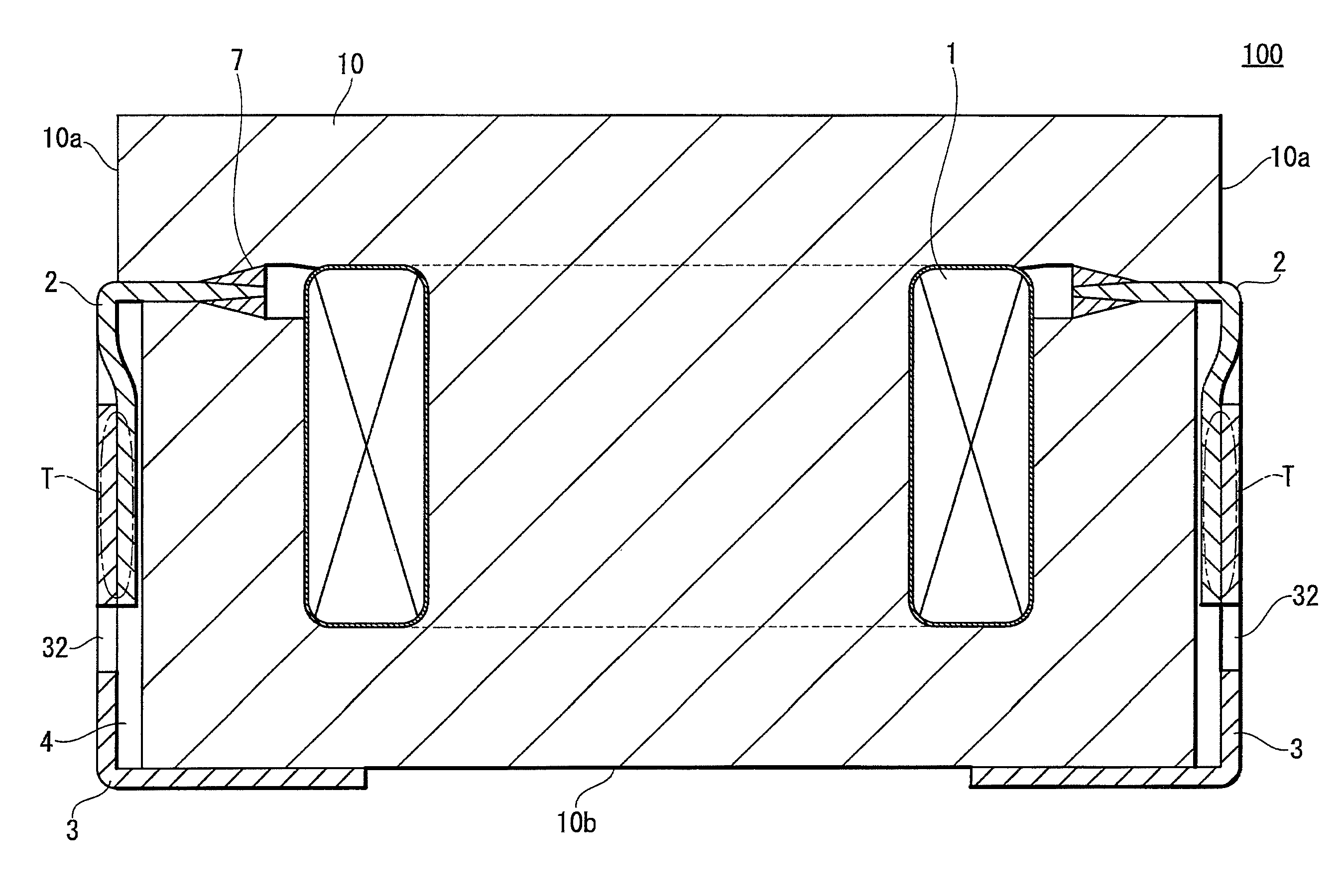
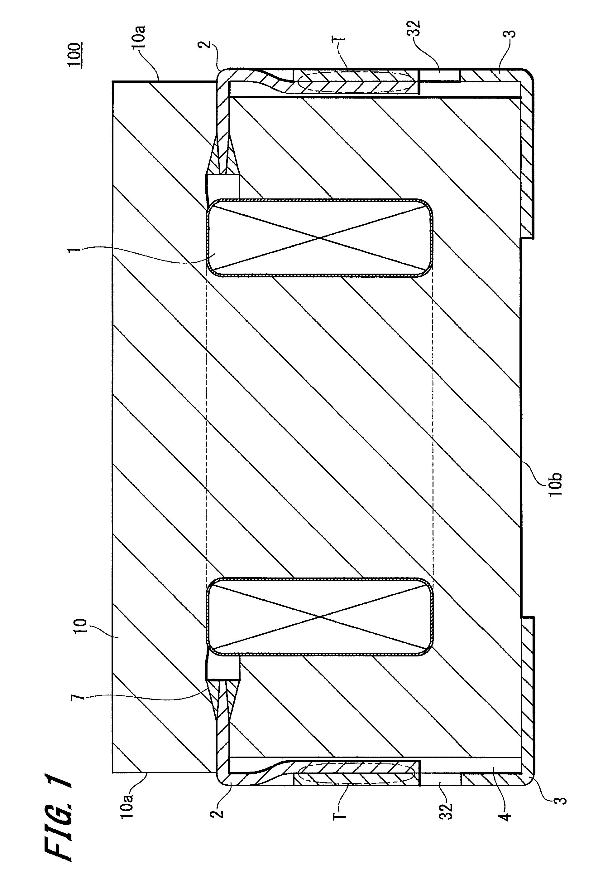
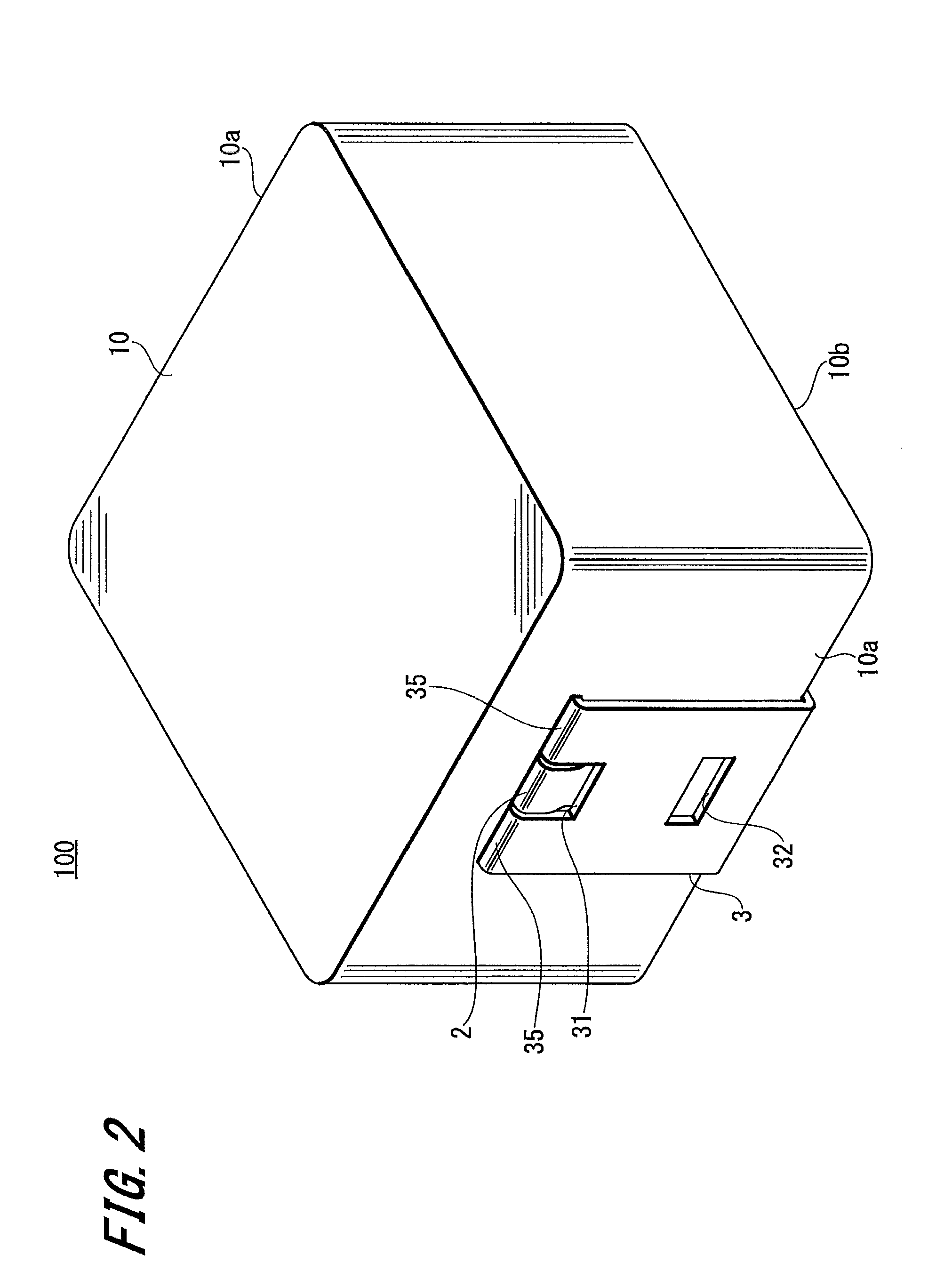
[0048]FIG. 1 is a cross section of a coil component 100 according to the present embodiment. FIG. 2 is a perspective view, FIG. 3 is a top view, FIG. 4 is a side view, and FIG. 5 is a bottom view. Note that FIG. 1 shows a cross section at X-X′ of FIG. 3.

[0049]The coil component 100 according to the present embodiment includes, as illustrated in FIG. 1, a magnetic core 10 made of a magnetic material for example, a coil 1 embedded in the core 10, and a terminal 3 connected with a coil terminal 2 of the coil 1.

[0050]The magnetic material constituting the core 10 is not limited here in particular, and for example, Mn—Zn ferrite, Ni—Zn ferrite, sendust alloy, permalloy, etc. are given. The core 10 is formed by pressure molding and baking granulation powder in which the magnetic ...

second embodiment

[0097]2. Second Embodiment

[0098]Next, description will be made below referring to FIG. 9 and FIG. 10 with respect to a coil component according to the second embodiment of the present invention.

[0099]FIG. 9 is a schematic cross section illustrating a constitution of a coil component 200 according to the second embodiment. Note that parts corresponding to those in the first embodiment (FIG. 1 through FIG. 5) are denoted with the same symbols, and description thereof is omitted.

[0100]The coil component 200 according to the second embodiment includes the coil 1 in which for example a round or flat rectangular conductive wire has been wound, the core 10 formed of a magnetic material and embedding therein the coil 1, and the terminal 3 connected with the coil terminal portion 2 of the coil 1.

[0101]A part of the coil terminal portion 2 is arranged outside of the core 10 and is bent downward along the side surface 10a of the core 10. The terminal 3 in a shape of a flat plate is partly embe...

third embodiment

[0115]3. Third Embodiment

[0116]FIG. 11 is a cross section of a coil component 300 according to the third embodiment of the present invention. FIG. 12 is a perspective view of the coil component 300, and FIG. 13 is a perspective view of the coil component 300 viewed from below before the protruded part of the terminal 3 and the protruded part of the coil terminal portion 2 are bent.

[0117]Note that parts corresponding to those in the second embodiment are denoted with the same symbols, and overlapped description thereof is omitted.

[0118]The coil component 300 according to the present embodiment includes the coil 1 in which a conductive wire has been wound, the core 10 formed of a magnetic material and embedding therein the coil 1, and the terminal 3 connected with the coil terminal portion 2 of the coil 1.

[0119]The above-described constitution is substantially the same as that illustrated in the second embodiment. However, in the present embodiment, the length and the width of the sec...


PUM

PropertyMeasurementUnit
conductiveaaaaaaaaaa
electrical continuityaaaaaaaaaa
heat resistanceaaaaaaaaaa

Abstract

A coil component includes a core formed by a magnetic material, a coil embedded in the core, a part of a terminal portion of the coil protruded from a side surface of the core, and a tabular terminal, a part thereof protruded from the side surface of the core and partly connected with the protruded part of the terminal portion of the coil. The protruded part of the terminal portion of the coil and the protruded part of the tabular terminal are respectively bent toward the bottom surface side of the core along the side surface of the core, and the protruded and bent part of the terminal portion of the coil is arranged between the protruded and bent part of the tabular terminal and the core.

Description

BACKGROUND OF THE INVENTION[0001]1. Field of the Invention[0002]The present invention relates to a coil component used in various electric appliances, electronic devices, etc.[0003]2. Description of Related Art[0004]Known coil components include the one in which a coil formed by winding a conductive wire is embedded in a magnetic core formed of a magnetic material, as described for example in the following Patent Document 1.[0005]In the coil component described in Patent Document 1, a coil is embedded in a magnetic core, and lead-out wires of the coil protrude from side surfaces of the coil.[0006]Also, parts of terminals of the coil component are embedded in the magnetic core, and remaining portions of the terminals similarly protrude from the side surfaces of the magnetic core. The terminals and the lead-out wires of the coil are overlapped to be connected with each other and thereby electrical continuity is established between the terminals and the coil.[0007]According to Patent D...

Claims


Application Information

Patent Timeline
Patent Type & Authority Patents(United States)
IPC IPC(8): H01F27/29
CPCH01F27/292H01F41/10Y10T29/49073H01F2017/048H01F17/04Y10T29/49071H01F27/29
Inventor YAMADA, SATORUHATAYAMA, YOSHIYUKI
Owner SUMIDA CORP
Why Eureka
Try Eureka