
Coil component
a coil and component technology, applied in the field of coil components, can solve the problems of difficult to ensure high accuracy in bending the terminal, and achieve the effect of improving the overall size of the coil component and satisfactory overall siz
- Summary
- Abstract
- Description
- Claims
- Application Information
AI Technical Summary
Benefits of technology
Problems solved by technology
Method used
Image

Examples
first embodiment
[0040]1. First Embodiment
[0041]1-1. Constitution of Coil Component
[0042]1-2. Production Method of Coil Component
second embodiment
[0043]2. Second Embodiment
[0044]3. Third Embodiment
[0045]1. First embodiment
[0046]1-1. Constitution of Coil Component
[0047]First, using FIG. 1 through FIG. 5, description is made with respect to a constitution of a coil component according to the first embodiment.
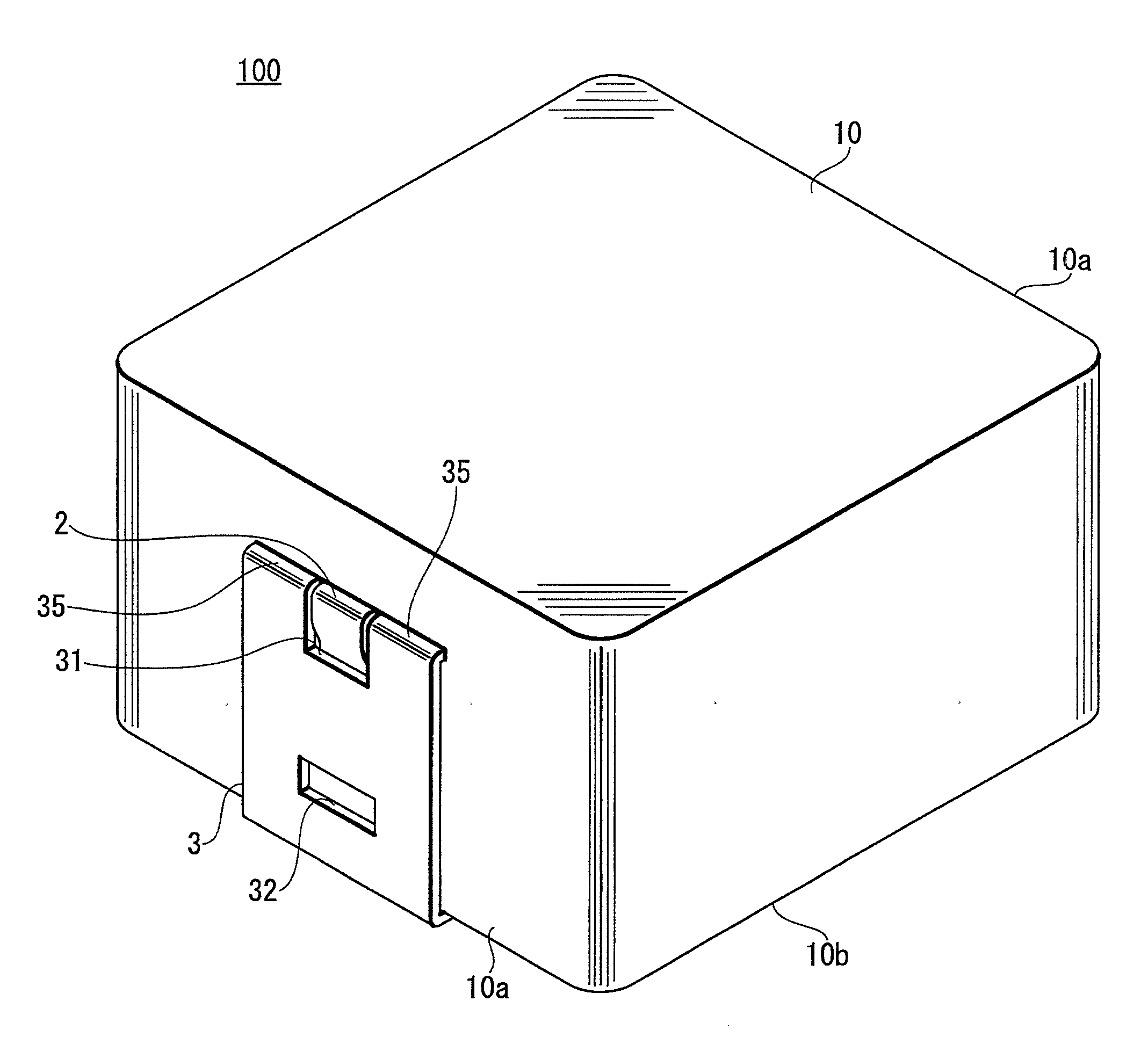
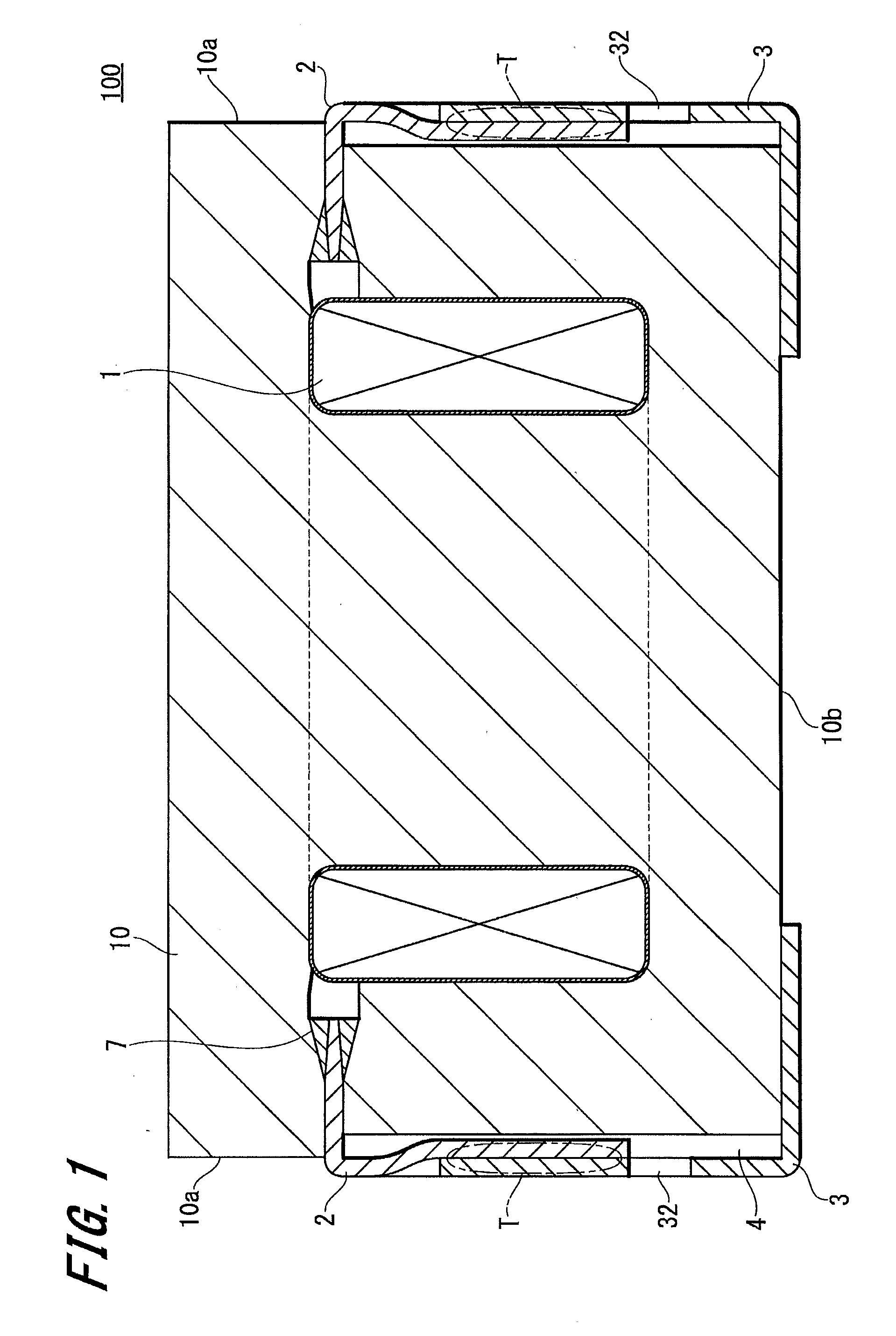
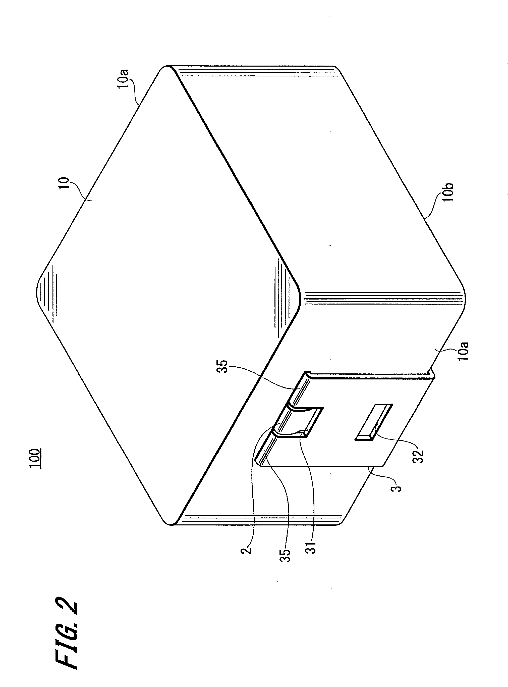
[0048]FIG. 1 is a cross section of a coil component 100 according to the present embodiment. FIG. 2 is a perspective view, FIG. 3 is a top view, FIG. 4 is a side view, and FIG. 5 is a bottom view. Note that FIG. 1 shows a cross section at X-X′ of FIG. 3.
[0049]The coil component 100 according to the present embodiment includes, as illustrated in FIG. 1, a magnetic core 10 made of a magnetic material for example, a coil 1 embedded in the core 10, and a terminal 3 connected with a coil terminal 2 of the coil 1.
[0050]The magnetic material constituting the core 10 is not limited here in particular, and for example, Mn—Zn ferrite, Ni—Zn ferrite, sendust alloy, permalloy, etc. are given. The core 10 is formed by pressure molding a...
third embodiment
[0115]3. Third Embodiment
[0116]FIG. 11 is a cross section of a coil component 300 according to the third embodiment of the present invention. FIG. 12 is a perspective view of the coil component 300, and FIG. 13 is a perspective view of the coil component 300 viewed from below before the protruded part of the terminal 3 and the protruded part of the coil terminal portion 2 are bent.
[0117]Note that parts corresponding to those in the second embodiment are denoted with the same symbols, and overlapped description thereof is omitted.
[0118]The coil component 300 according to the present embodiment includes the coil 1 in which a conductive wire has been wound, the core 10 formed of a magnetic material and embedding therein the coil 1, and the terminal 3 connected with the coil terminal portion 2 of the coil 1.
[0119]The above-described constitution is substantially the same as that illustrated in the second embodiment. However, in the present embodiment, the length and the width of the sec...
PUM
| Property | Measurement | Unit |
|---|---|---|
| conductive | aaaaa | aaaaa |
| electrical continuity | aaaaa | aaaaa |
| heat resistance | aaaaa | aaaaa |
Abstract
Description
Claims
Application Information