[0007]This devices and methods described herein provide for placement of chest tubes in contaminated environments using rapid deployment techniques, for maintaining sterility at the penetration site on the patient's chest where the chest tube emerges, and for improved methods of holding the chest tube in place. The present invention is a chest tube that is provided with a double aseptic
package that maintains sterility and cleanliness of the chest tube in contaminated environments. The chest tube includes a cannula with a sharpened distal end and a blunt trocar or
nose cone that selectively shields or exposes the sharpened distal end.
[0009]The chest tube may further include a malleable region along part or all of its length to facilitate bending of the chest tube into a pre-determined shape. The use of a curved or bent shape on the part of the chest tube facilitates placement beneath the ribs but above the lungs and heart.
[0011]In another embodiment of the invention, a chest tube is designed with an integral tip that permits the chest tube to be advanced out of the
package by forcing a fenestration in the package wall or seal. The integral tip may be a
cutting member that is selectively exposed by the operator and then retracted following package penetration. This same cutting member may also be used to make the initial incision in the chest wall of the patient. The member that re-protects the cutting edge may be a blunt
nose that is suitable for bluntly dissecting the tissue between the ribs. In another embodiment of the invention, the blunt
nose is configured to form a wedge so that it is able, itself, to force a fenestration in the package or package seal, thus obviating the cutting edge.
[0013]To facilitate placement of the chest tube, a specialized cutter is configured to perform the initial incision into the chest wall without penetrating below the level of the ribs. This specialized cutter comprises safety features to prevent premature deployment and to prevent cutting too deeply into the chest. This cutter is actuated by manual, electrical or hydraulic / pneumatic force. It may be configured to be a positive displacement cutter or it may be a punch that is loaded and fired or activated under pre-determined force.
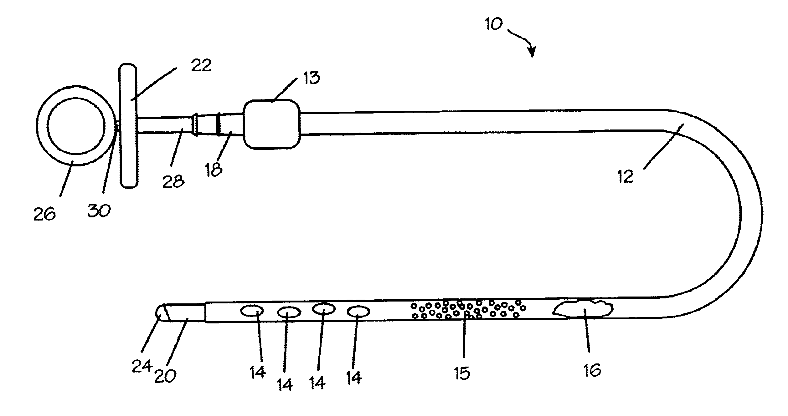
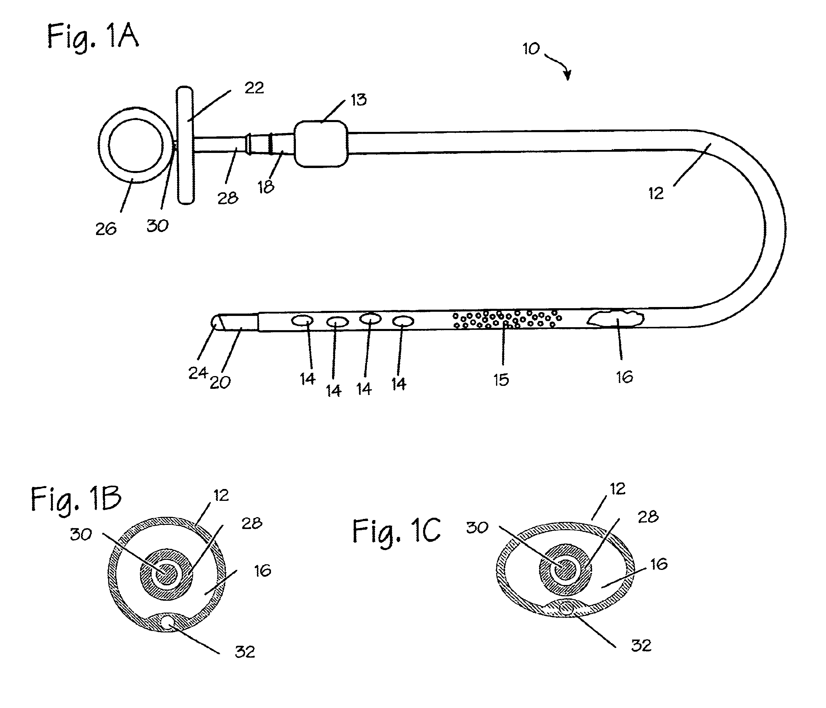
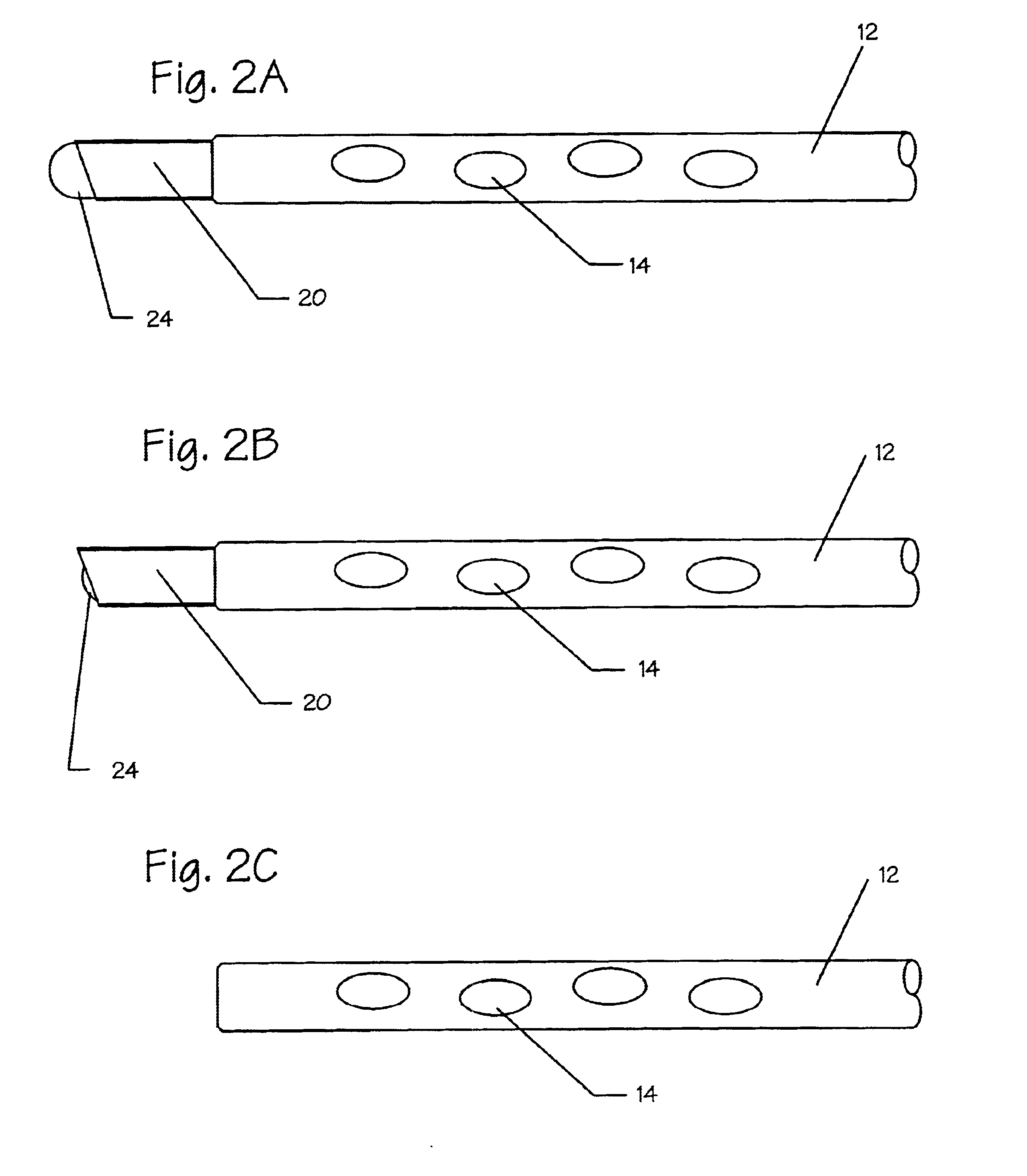
[0014]The chest tube comprises a short insertion portion (the
distal segment intended and adapted for insertion into the body of the patient) and a stop to prevent it from being inserted too far into the patient. The short insertion portion has a blunt distal end and is capable of being inserted into a fenestration or incision in the chest wall that was created by either a scalpel and
blunt dissection as would be performed by a gloved finger, a Kelly clamp, or a specialized trocar and obturator. The short chest tube is inserted through the incision into the
chest cavity. The short chest tube projects through the
skin, fat,
fascia, between the ribs, and finally through the pleural lining. The tip of the chest tube is soft or blunt or both, and contains no edges or roughness that might erode underlying tissues. The short chest tube is terminated on its proximal segment (proximal to the stop) with a manually openable and closeable valve or it is terminated with a one-way valve that permits only removal of fluids and air from the chest cavity. The short chest tube comprises a
flange that prevents excessive penetration into the chest cavity. The
flange is designed to stop at the level of the
skin surface, or, in another embodiment, the
flange is smaller and is inserted into the incision but does not penetrate below the level of the top of the ribs.
[0015]In yet another embodiment, should lateral penetration of the chest tube be desirable, the short chest tube comprises a trocar and obturator that bluntly penetrates the incision to a pre-determined depth such that it is depth-limited. The trocar further comprises a right angle turn at its distal end that serves to deflect a secondary longer chest tube that is placed through the trocar and which extends laterally in the pleural space to the desired location. The trocar and secondary chest tube comprise a seal
system to prevent gas passage between the two components. The trocar further comprises an
angular orientation marker that provides an indication to the operator of the direction where the secondary chest tube will be deflected. The orientation markers may be aligned by the practitioner to point to the head or the feet (or other
anatomical landmark) so that the deflection is always in a pre-determined direction.

