Method and apparatus for rapid deployment chest drainage

a chest and chest technology, applied in the field of general surgery, cardiothoracic surgery, trauma surgery, combat medicine, etc., can solve problems such as contaminated environments, and achieve the effect of reducing the risk of infection

Inactive Publication Date: 2005-10-20
DAMAGE CONTROL SURGICAL TECH
View PDF12 Cites 37 Cited by
  • Summary
  • Abstract
  • Description
  • Claims
  • Application Information

AI Technical Summary

Benefits of technology

[0019] In another embodiment of the chest tube, the central or through lumen of the chest tube and the fenestrations or openings at the distal tip are coated with anti-thrombogenic agents such as but not limited to heparin. Heparin may be covalently or ionically bonded to the polymeric material of the chest tube. The exterior and interior surfaces of the chest tube are optionally also coated with antibiotic materials to minimize the risk of infection.
[0020] For purposes of summarizing the invention, certain aspects, advantages and novel features of the invention are described herein. It is to be understood that not necessarily all such advantages may be achieved in accordance with any particular embodiment of the invention. Thus, for example, those skilled in the art will recognize that the invention may be embodied or carried out in a manner that achieves one advantage or group of advantages as taught herein without necessarily achieving other advantages as may be taught or suggested herein. These and other objects and advantages of the present invention will be more apparent from the following description taken in conjunction with the accompanying drawings.

Problems solved by technology

Such contaminated environments may occur in the pre-hospital setting or military setting where rain, mud, or other elements exist.

Method used


Image

  • Method and apparatus for rapid deployment chest drainage
  • Method and apparatus for rapid deployment chest drainage
  • Method and apparatus for rapid deployment chest drainage

Examples


Embodiment Construction

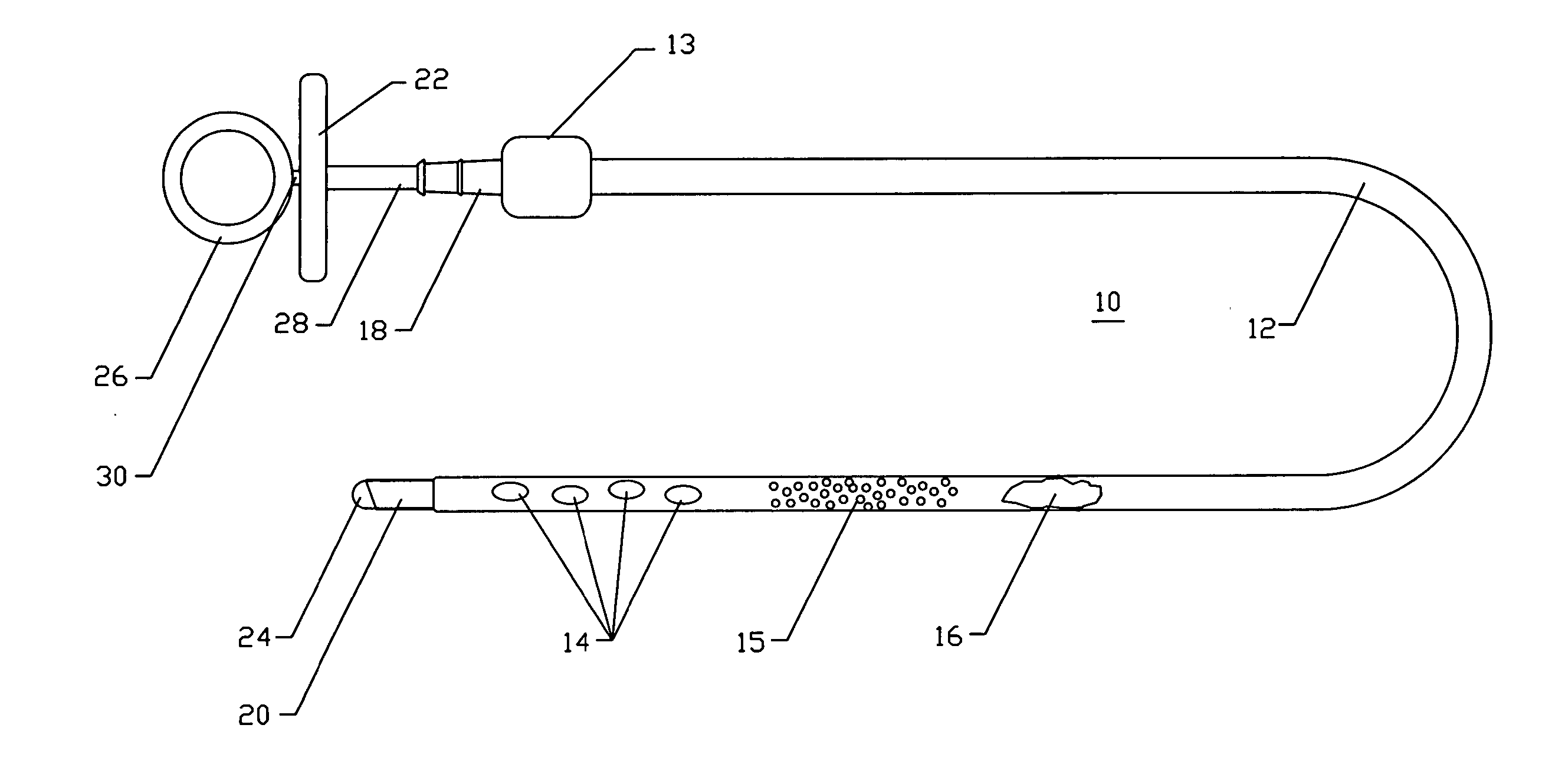
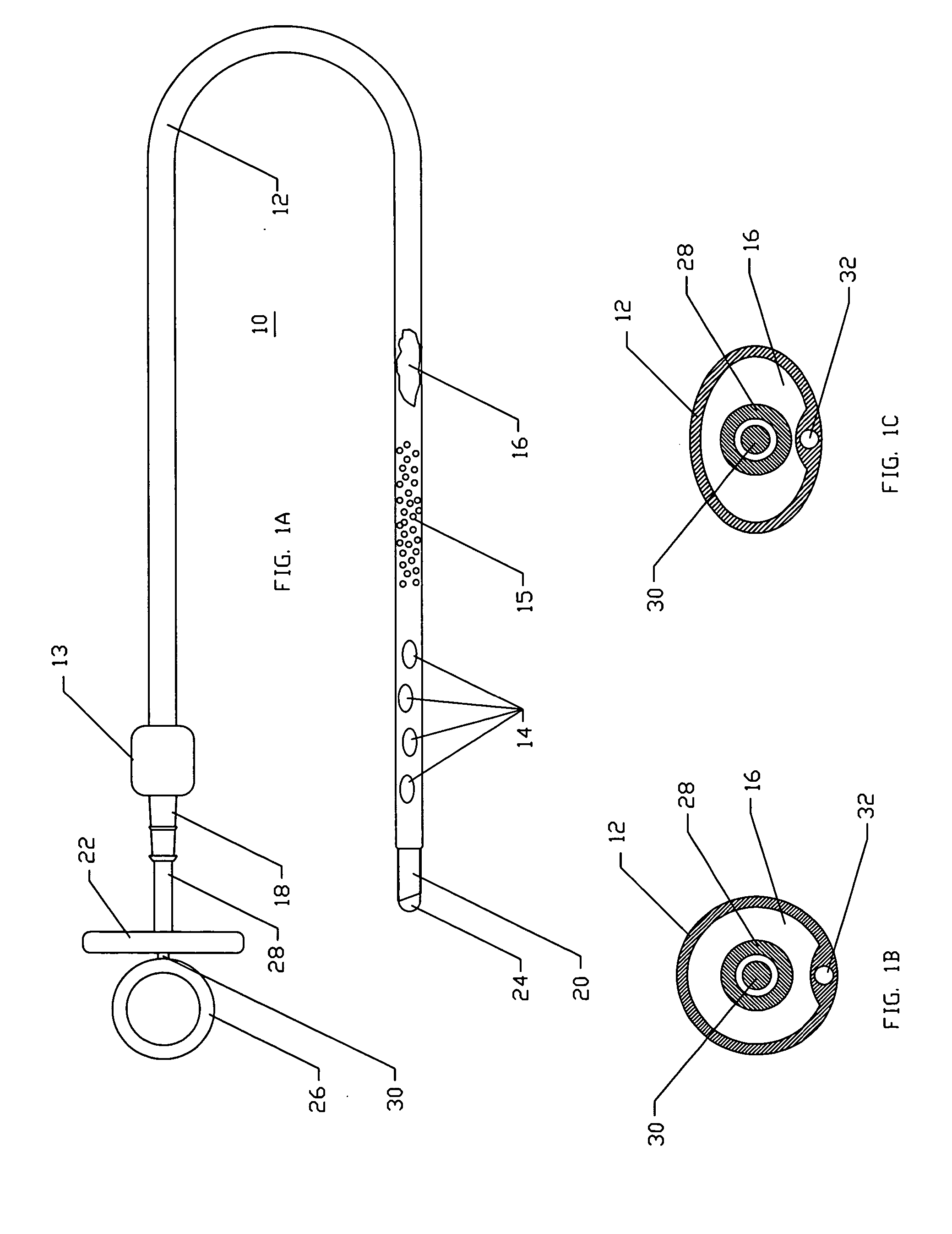
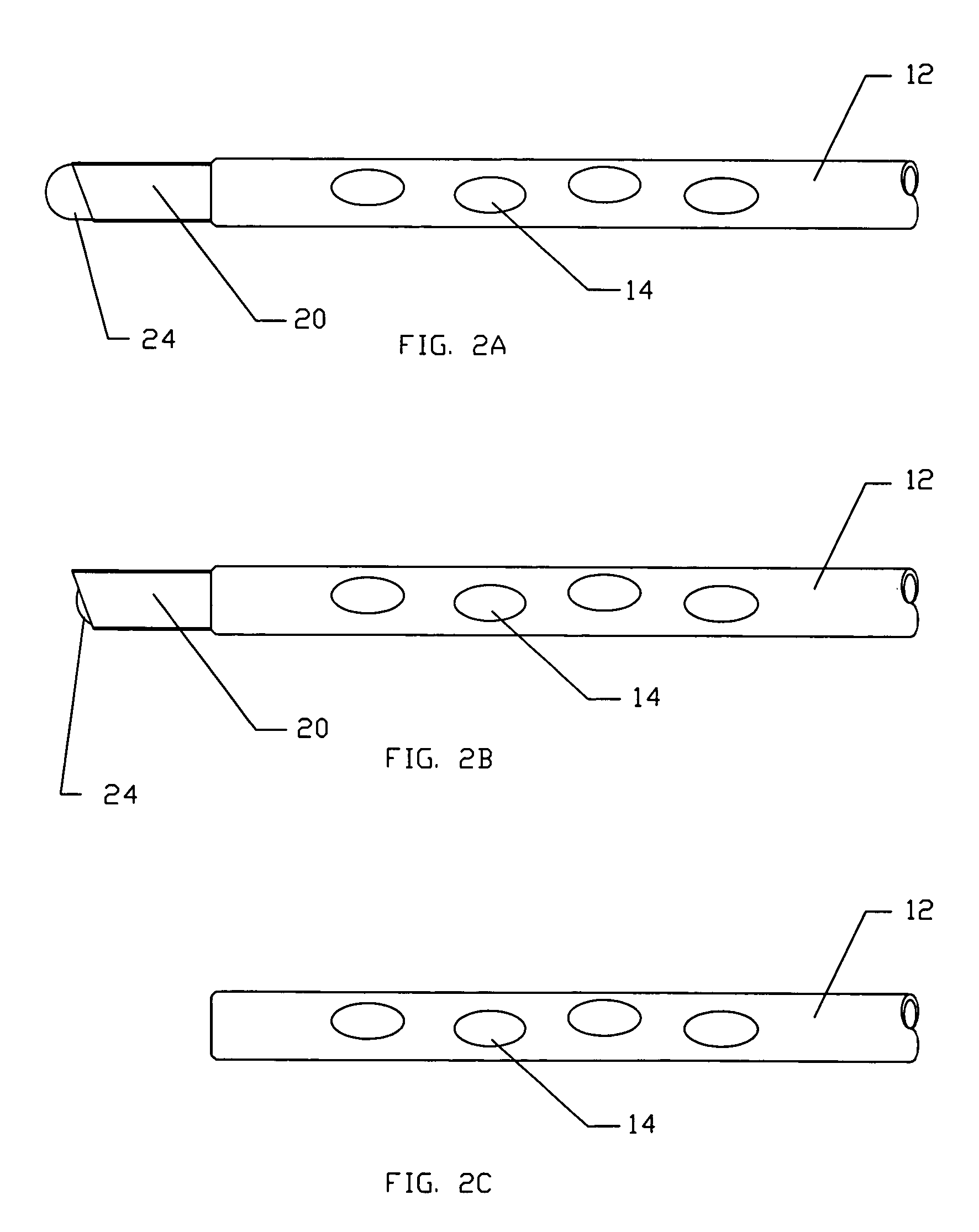
[0050] In accordance with one or more embodiments of the present invention, a chest tube, packaging and accessory components are described herein. In order to fully specify this preferred design, various embodiment specific details are set forth, such as the number and makeup of the hold-down straps, cutter action and packaging materials. It should be understood, however that these details are provided only to illustrate the presented embodiments, and are not intended to limit the scope of the present invention.

[0051] The invention, which is generally termed a catheter or cannula, can be described as being an axially elongate hollow tubular structure having a proximal end and a distal end. The axially elongate structure further has a longitudinal axis and has an internal through lumen that extends from the proximal end to the distal end for the passage of instruments, fluids, tissue, or other materials. The axially elongate hollow tubular structure is generally flexible and capable...


PUM


Abstract

Devices and methods are disclosed for achieving chest drainage in humans or other animals. Chest drainage is often required following traumatic injury or surgery. The devices and methods disclosed herein are especially useful in the emergency, trauma surgery or military setting. The devices utilize a chest tube with a cutting distal end and a central blunt trocar. The blunt trocar or obturator shields the sharp cutting distal end of the chest tube until controllably retracted. Once the blunt trocar or obturator is retracted, the chest tube is advanced out through its sterile, protective package and into the patient. The blunt trocar is advanced back into its position to shield the sharp tip of the chest tube during patient insertion. The chest tube also includes a hold-down mechanism that is created by an adhesive seal to the patient's chest and ribbons or straps that are wrapped around the chest tube once it is correctly positioned. The straps include adhesive ends to grip the chest tube once the straps are in place.

Description

PRIORITY CLAIM [0001] This application is a continuation-in-part of U.S. patent application Ser. No. 10 / 676,562 filed Sep. 30, 2003, the entirety of which is hereby included herein by reference.FIELD OF THE INVENTION [0002] The inventions described below relate to the fields of general surgery, cardiothoracic surgery, trauma surgery, combat medicine, and emergency medical services. BACKGROUND OF THE INVENTION [0003] Chest drainage tubes are flexible tubes that are placed into a patient's chest cavity to allow for drainage of fluids following trauma or surgery. These chest tubes have one or more holes at the distal end through which the fluid is evacuated from the chest cavity into the lumen of the chest tube. The proximal end of the chest tube includes connectors to allow for passage of the drained fluids from the lumen of the chest tube into a collection device or apparatus. The chest tubes or collection apparatus typically include features to prevent backflow of air into the chest...

Claims


Application Information

Patent Timeline
Patent Type & Authority Applications(United States)
IPC IPC(8): A61B17/20A61B17/34A61M1/00
CPCA61B17/3415A61M1/008A61B2217/005A61B17/3439A61M1/84
Inventor BUCKMAN, ROBERT F.LENKER, JAY A.KOLEHMAINEN, DONALD J.
Owner DAMAGE CONTROL SURGICAL TECH
Why Eureka
Try Eureka