Supercharge Your Innovation With Domain-Expert AI Agents!

Display device

a technology of a display device and a display screen, which is applied in the direction of discharge tube main electrodes, lighting and heating apparatus, instruments, etc., can solve the problems of low conversion efficiency of light, uneven brightness, and reduced reliability of elements, so as to reduce temperature distribution and reduce heat loss, the effect of local cooling efficiency

Active Publication Date: 2012-06-26
MITSUBISHI ELECTRIC CORP
View PDF25 Cites 2 Cited by
  • Summary
  • Abstract
  • Description
  • Claims
  • Application Information

AI Technical Summary

Benefits of technology

The present invention relates to a display device using a light emitting element group for display. The invention aims to efficiently cool the substrate where the light emitting elements are arranged, while suppressing the rise in temperature and achieving uniform temperature distribution. The invention includes a substrate, an air duct plate, a case body, and a fan. The fan sends an air into a space that is surrounded by the case body and air duct plate. The air duct plate has openings acting to blow the cooling air generated by the fan to a predetermined portion on the substrate. The cooling efficiency is locally increased by forming each opening at a position corresponding to a local heat generation source or to a region of stagnation of the cooling air. The invention provides a display device that can suppress the rise in temperature and achieve uniform temperature distribution without incurring excessive rise in cost and complicated structure.

Problems solved by technology

However, in these display devices, a conversion efficiency of light is low, and, for example, as to LED elements, it is about 10% and most supplied power is to be converted to heat.
Furthermore, the rise in temperature of the above-mentioned elements further decreases the conversion efficiency of light, thus to be the cause of reduction in reliability of elements and uneven brightness.
In particular, in the case that elements of displaying colors (for example, elements of displaying a red color, blue color and green color) have different light conversion efficiencies, this fact is to be a primary factor of generation of irregular colors, and a problem exits in, e.g., the reduction in quality of images.

Method used


Image

  • Display device
  • Display device
  • Display device

Examples


embodiment 1

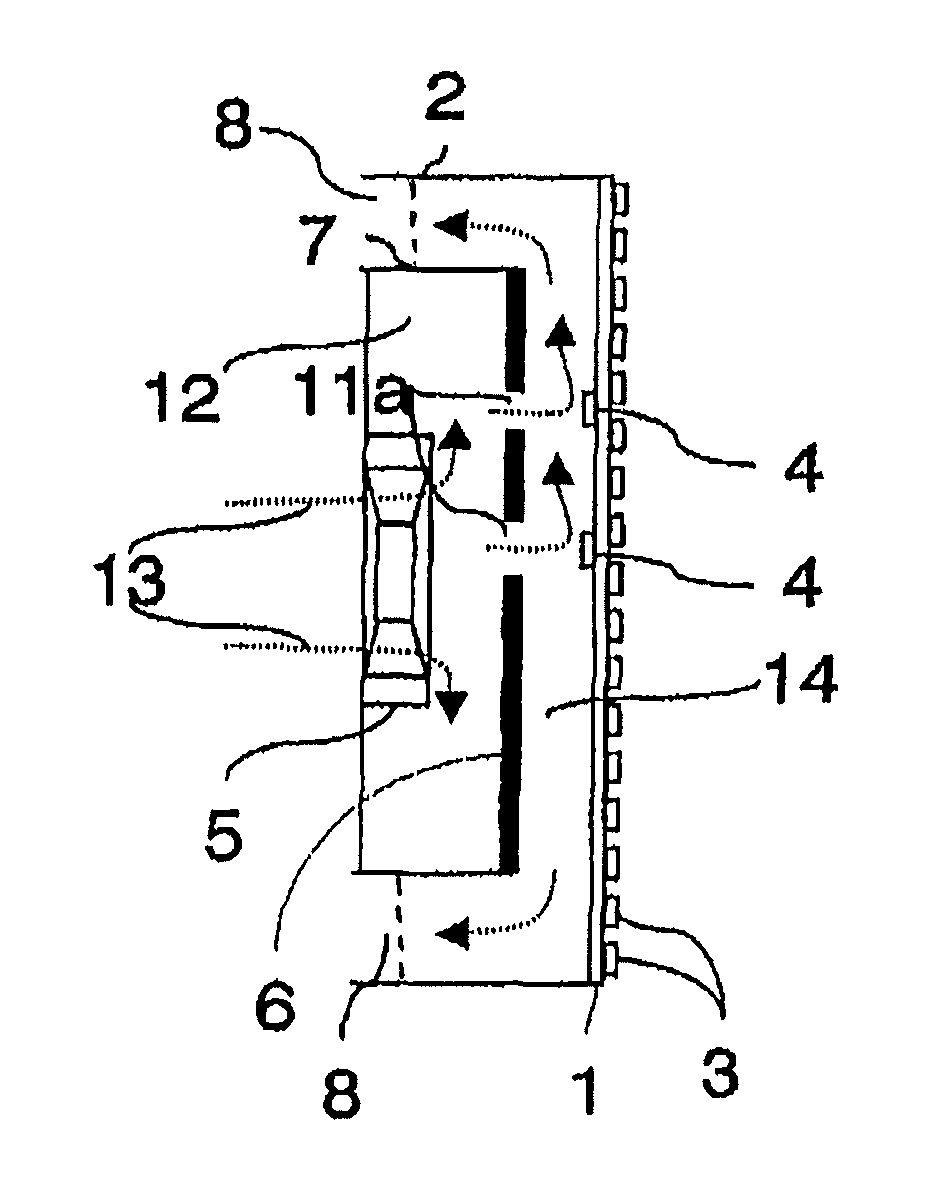
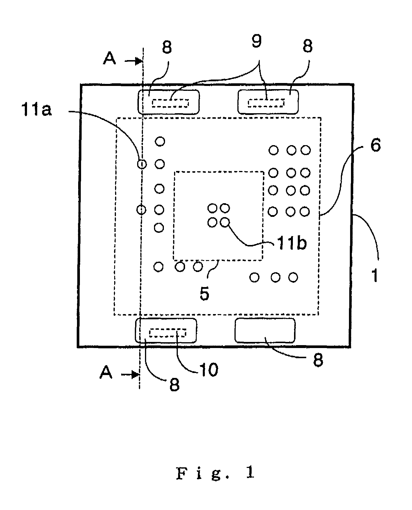
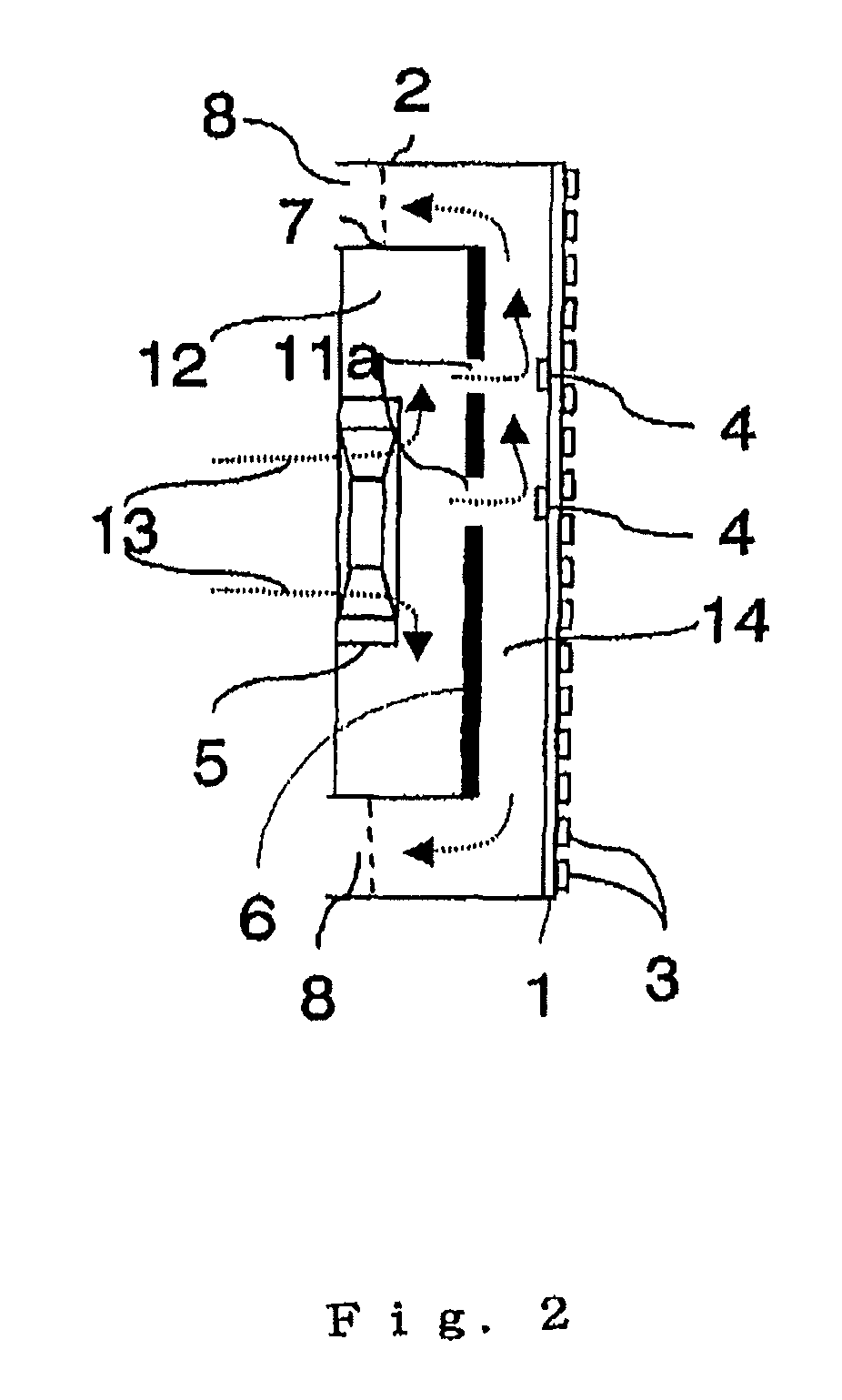
[0017]A preferred embodiment according to the present invention is hereinafter described in detail referring to the accompanying drawings. FIG. 1 is a schematic diagram of a display device according to a first embodiment of the present invention viewed from backside. And FIG. 2 is a diagram schematically illustrating a cross section taken along the line A-A of FIG. 1. A plurality of such display units as illustrated in the drawings are arranged lengthwise and crosswise to form a display device of a large screen as a whole. Incidentally, although in FIG. 2, there is no fan present in the cross section taken along the line A-A, for reasons of convenience of explanation, it is illustrated at a position being projected on the cross section taken along the line A-A.

[0018]In the drawings, reference numeral 1 designates a substrate supported by a substrate support 2 on the surface side of a display device, numeral 3 designates, for example, an LED element group of a plurality of LED elemen...


PUM


Abstract

An air duct plate is provided on the back of a substrate on the surface of which a light emitting element group for display as well as an integrated circuit are disposed. A fan acts to send air into a space surrounded by a case body extending over and around the air duct plate and the air duct plate. A plurality of openings acting to blow a cooling air generated by the fan to a predetermined portion of the substrate are formed in the air duct plate.

Description

TECHNICAL FIELD[0001]The present invention relates to a display device causing a light emitting element group to emit light to make a display and, more particularly, to a display device that can suppress the rise of temperature resulted from heat generation accompanied by light emission of a light emitting element group as well as temperature distribution.BACKGROUND ART[0002]Recently, display devices using a plasma display, a liquid crystal display, a field emission display and the like including a light emitting diode (hereinafter, it is abbreviated as LED (Light Emitting Diode)) have been generally known and have been widely employed together with those using a conventional CRT (Cathode Ray Tube), a discharge tube or the like, or in substitution for them.[0003]However, in these display devices, a conversion efficiency of light is low, and, for example, as to LED elements, it is about 10% and most supplied power is to be converted to heat. Furthermore, the rise in temperature of th...

Claims


Application Information

Patent Timeline
Patent Type & Authority Patents(United States)
IPC IPC(8): H05K7/20G09G3/20G09G5/10G09G3/36F21V8/00F21V29/00H01J61/52
CPCH05K7/20972Y10S345/905
Inventor IOKI, KAZUHIROMORI, SHOJIIWASAKI, YOSHIMIKISE, KOJI
Owner MITSUBISHI ELECTRIC CORP
Features
  • R&D
  • Intellectual Property
  • Life Sciences
  • Materials
  • Tech Scout
  • Unparalleled Data Quality
  • Higher Quality Content
  • 60% Fewer Hallucinations
Learn More