Deep drawn nozzle for precision liquid dispensing

a precision liquid and nozzle technology, applied in the field of nozzles, can solve the problems of underfilling the device, increasing the stress on the solder joints, and reducing the viscosity of the liquid, so as to achieve the effect of reducing the viscosity and easy and accurate application

Inactive Publication Date: 2012-07-03
VERRILLI BRIAN +1
View PDF6 Cites 2 Cited by
  • Summary
  • Abstract
  • Description
  • Claims
  • Application Information

AI Technical Summary

Benefits of technology

[0010]This invention is a metal nozzle, containing a high percentage of copper, having an internal and external smooth and very thin wall, for delivering a measured quantity of viscous liquid, generally in a heated condition and injecting it next to the narrow underspace of a micro-chip device solder-mounted on a carrier board wherein the nozzle comprises an upper flared opening, defined by a horizontal perimeter, and a flare wall extending inward from the perimeter, a cylindrically-shaped barrel wall extending from the flare wall downward to a break point defined by a circle parallel to the flare opening and spaced-apart therefrom, a cone-shaped wall extending downward from the circular break point and inward therefrom to a circular exit opening at a rate of convergence lying between 5° and 20°, and more particularly 10°, and a small-diameter exit tube extending from the circular exit opening, at one end of the tube, to a circular exit aperture, at the other, spaced-apart end of the tube where the ratio between the inside diameter of the exit tube to the wall thickness of the exit tube is at least 7.5 and preferably larger. The flared opening is arranged to fit into a Luer connection or other connection. The Luer connection is connected in turn to a first hose that is connected to a transfer hose that is connected to a pump and to a reservoir of the liquid epoxy. Heating coils are arranged near or around the nozzle to allow final heating of the liquid, to reduce its viscosity and allow it to be more easily and accurately applied next to the underspace without requiring a significant amount of pump power.
[0012]Accordingly, the main object of this invention is a novel nozzle that allows a large amount of heat transfer in a short amount of time to lower the viscosity of the dispensable liquid. Other objects of the invention include a low cost nozzle having a short, wide, transfer barrel for transferring the liquid from the first hose to the point of dispense; a nozzle that has a wide barrel and a conical entry spout to lower the required pump pressure of the adhesive; a nozzle with a very short run of small diameter tubing to reduce the pressure drop of the liquid over the length of the nozzle; a nozzle with a low, smooth-walled interior profile that does not accumulate unwanted buildup on the tip nor allow the liquid to hang up in the barrel; a nozzle with a thin wall able to dispense liquid close to the device; and, a nozzle made with a low cost process that allows the nozzles to be made more economically and more useful in the relevant industry.

Problems solved by technology

The component often becomes hot during its use in the computer circuit and this heat causes the chip to expand thereby causing stress in the solder joints.
In addition, the computer is often of the portable variety where it may be dropped or otherwise subjected to physical shock thus placing an even greater stress on the solder joints.
While the microchip, with heated liquid adhesive, seemed to be the answer to the problem, a new problem developed, namely how to design an economical nozzle to apply the viscous liquid onto the device.
The nozzle needs to be dimensionally stable under pressure so that each injection of the liquid is of a predictable volume where not too much liquid is injected, resulting in overfilling and running into areas where its presence is detrimental, or not too little liquid is injected, resulting in underfilling the device thereby reducing the inherent benefits of the liquid.
The problem with modified hypodermic needles is that a constant diameter throughout the length of the needle causes a very high pressure drop across the needle and restricts liquid flow.
Stainless steel and plastic are not known as a good heat transfer materials.
However, a machined nozzle is limited to the size of the tools that can be used to cut the inside wall diameter.
This limitation, along with the high cost of machining minute nozzles of this type, has slowed the widespread use of such nozzles in the industry.
The molded plastic nozzle can be made in a variety of sizes and shapes; however, because plastics are not good heat transfer agents nor dimensionally stable, such a practice has not been well accepted in the industry and the modified hypodermic needle remains the most widely used nozzle.

Method used


Image

  • Deep drawn nozzle for precision liquid dispensing
  • Deep drawn nozzle for precision liquid dispensing
  • Deep drawn nozzle for precision liquid dispensing

Examples


Embodiment Construction

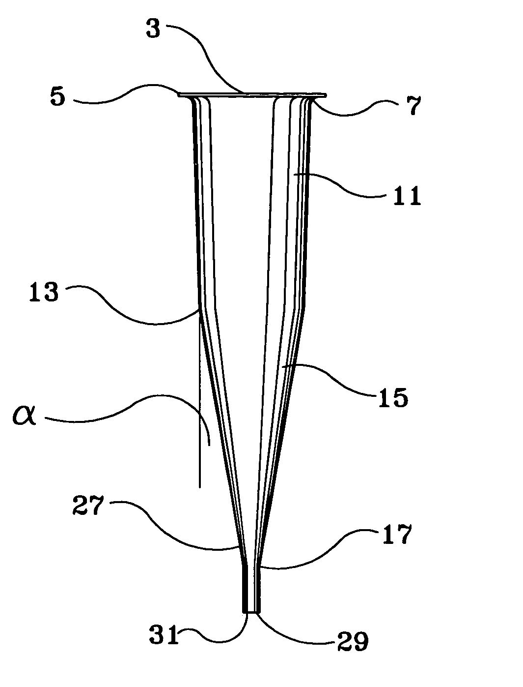
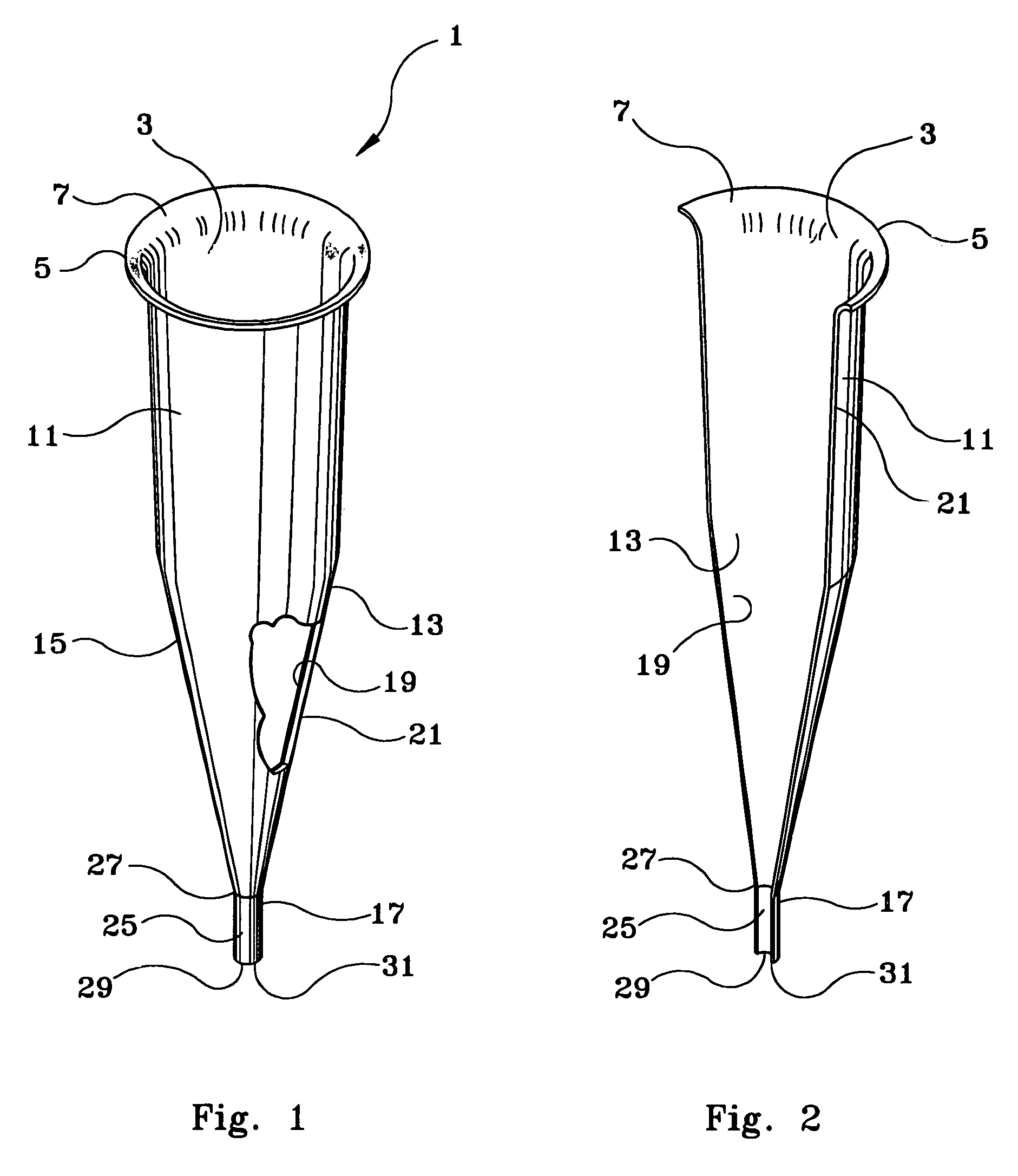
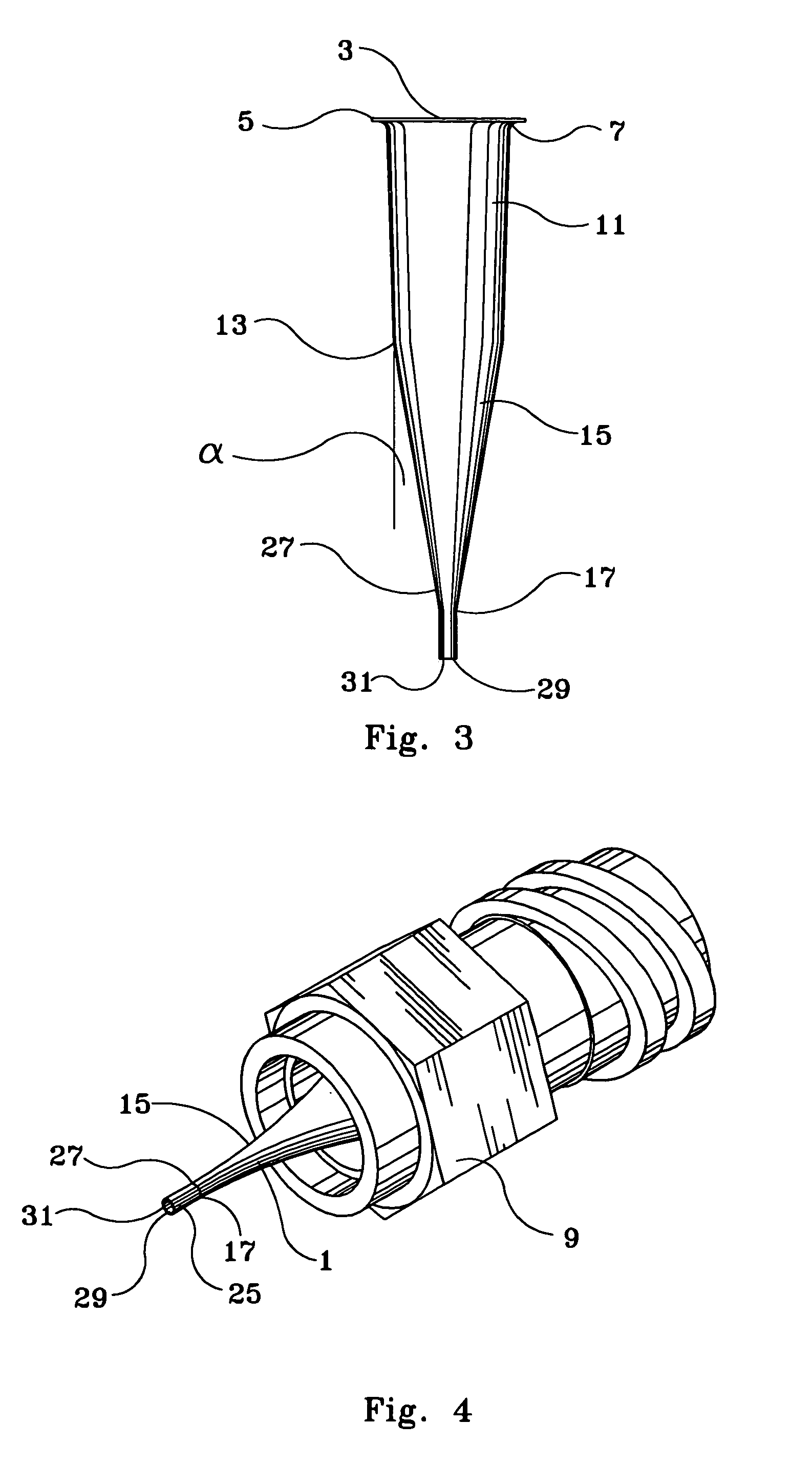
[0018]Turning now to the drawings wherein elements are identified by numbers and like elements are identified by like numbers throughout the four figures, the inventive nozzle 1 is depicted in FIG. 4 in a horizontal attitude, in FIGS. 1-3, the inventive nozzle 1 is depicted in vertical or near-vertical attitude, and comprises an upper flared opening 3 defined by a horizontally arranged perimeter 5 and a flare wall 7, extending there between, inward from perimeter 5. The purpose of upper flared opening 3 is to enter into a leak-proof connection with a retention device 9, partially shown in FIG. 4, which usually joins to a valve for controlling the flow of liquid through nozzle 1.

[0019]A cylindrically-shaped barrel wall 11 extends from flare wall 7 downward to a break point defined by a circle 13 preferably arranged parallel to upper flared opening 3 and spaced-apart therefrom. Barrel wall 11 is made with a slight inward slant or cast, such as between 1° to 5° and more preferably abou...


PUM

PropertyMeasurementUnit
diameteraaaaaaaaaa
perimeteraaaaaaaaaa
angleaaaaaaaaaa

Abstract

A nozzle for delivering a measured quantity of viscous liquid including a flared opening defined by a horizontal perimeter and a flare wall extending inward from the perimeter, a cylindrically-shaped barrel wall extending from the flare wall downward to a break point defined by a circle parallel to the flare opening and spaced-apart therefrom, a cone-shaped wall extending downward from the circular break point and inward therefrom to a circular exit opening, and a small-diameter exit tube extending from the circular exit opening to a circular exit aperture.

Description

FIELD OF THE INVENTION[0001]This invention pertains to the field of liquid dispensing equipment. More particularly, it pertains to a novel nozzle that directs precise volumes of viscous curable and non-curable liquids into locations that require precise injection of these liquids such as in the computer circuit industry.DESCRIPTION OF THE PRIOR ART[0002]As the computer industry strives for more and more capability and, simultaneously, seeks to make computers smaller and more compact, the computer components, such as computer chips (known as “devices”) fastened to the carrier are being crowded closer and closer together. This crowding has spawned newer techniques for mounting the devices on the carrier, such as a circuit board or on a computer chip, and attaching the electronic connections extending from these devices to those in the carrier.[0003]In the practice of attaching computer circuit components to carriers, currently, the practice is to arrange the component connections unde...

Claims


Application Information

Patent Timeline
Patent Type & Authority Patents(United States)
IPC IPC(8): B05B1/00B05C5/02B21C23/00B21J5/00B21J5/10B21K21/10B21K21/16
CPCB05C5/02B21C23/00B21J5/00B21J5/10B21K21/16B21K21/10Y10T29/49405Y10T29/49432Y10T29/49426Y10T29/49428
Inventor NEWBOLD, JOHN D.VERILLI, BRIAN L.
Owner VERRILLI BRIAN
Why Eureka
Try Eureka