Branch meter with configurable sensor strip arrangement

a sensor strip and bench meter technology, applied in the direction of moving iron instruments, electric devices, instruments, etc., can solve the problems of easy configuration errors in installation of such a system and circuit breakers to trip

Active Publication Date: 2012-07-03
VERIS INDS
View PDF256 Cites 18 Cited by
  • Summary
  • Abstract
  • Description
  • Claims
  • Application Information

AI Technical Summary

Problems solved by technology

In this manner, if a load shorts and thereafter draws excessive current then the circuit breaker will trip.
Unfortunately, the installation of such a system is prone to configuration error by the installer.

Method used


Image

  • Branch meter with configurable sensor strip arrangement
  • Branch meter with configurable sensor strip arrangement
  • Branch meter with configurable sensor strip arrangement

Examples


Embodiment Construction

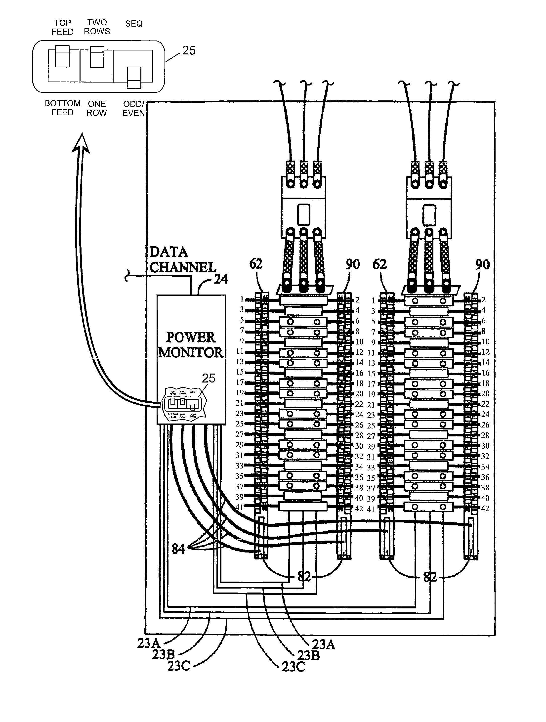
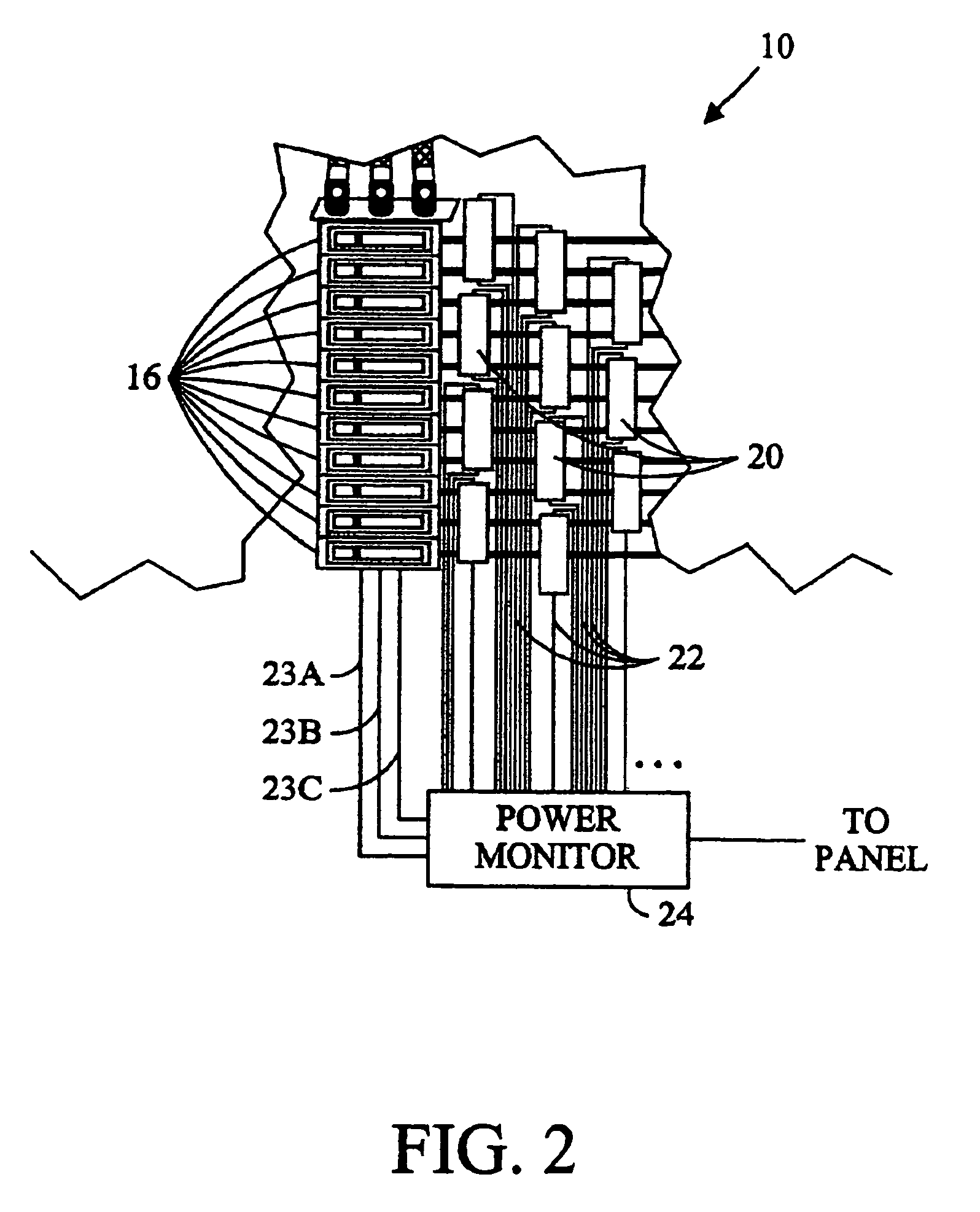
[0020]Referring to FIG. 2, to monitor the power provided to a particular load from one or more individual circuit breakers 16 a respective current sensor 20 may be interconnected to the wire on the load side of the respective circuit breaker 16. Typical circuit breakers may include a single phase, two phases, or three phases. The outputs 22 of each of the current sensors 20 may be interconnected to a power monitor 24. The current sensors 20 may be interconnected to one or more power monitors. Also, the current sensors 20 may likewise be daisy chained together, or interconnected to the power monitor(s) in any other suitable manner. An electrical interconnection from each bus bar to the power monitor(s) normally includes wires 23a, 23b, 23c, to sense the voltage and its corresponding phase relationship. Alternatively, the voltage potential and phase relationship for each phase may be sensed from locations other than the bus bars 14a, 14b, and 14c, such as for example, a wire provided ...


PUM


Abstract

A power monitoring system configurable to monitor electrical energy sensed by multiple sensors of one or more sensor arrays which may be organized in one of several array arrangements.

Description

CROSS-REFERENCE TO RELATED APPLICATIONS[0001]This application claims the benefit of U.S. Provisional App. No. 61 / 130,763, filed Jun. 2, 2008.BACKGROUND OF THE INVENTION[0002]The present invention relates to a power monitoring system.[0003]Referring to FIG. 1, many electrical power distribution systems include a panel enclosure 10 into which is provided electrical power using one or more sets of wires 12. The electrical power may have any voltage, any current, and any number of phases (e.g., single phase, two phases, or three phases). Each phase of the electrical power to the power panel is normally provided to a separate bus bar 14a, 14b, and 14c, which are normally elongate conductors within the power panel 10. A plurality of circuit breakers 16a, 16b, and 16c, etc., which trip or otherwise selectively disconnect electrical power, are electrically interconnected between one or more of the bus bars 14a, 14b, and 14c, and respective loads 18 external to the power panel 10. In many po...

Claims


Application Information

Patent Timeline
Patent Type & Authority Patents(United States)
IPC IPC(8): G01R21/00G01R19/00
CPCG01R21/00G01R22/065
Inventor PARKER, AARONDOLIM, GREGORY P.
Owner VERIS INDS
Why Eureka
Try Eureka