
Nerve cuff, method and apparatus for manufacturing same

a nerve cuff and manufacturing method technology, applied in the field of nerve cuffs, can solve the problems of nerve cuff damage, nerve damage, and difficulty in precisely determining the location of electrodes, and achieve the effect of avoiding nerve damage, avoiding nerve damage, and avoiding nerve damag

Inactive Publication Date: 2012-07-03
4491343 CANADA
View PDF10 Cites 146 Cited by
  • Summary
  • Abstract
  • Description
  • Claims
  • Application Information

AI Technical Summary

Benefits of technology

The design enhances selective nerve stimulation and recording capabilities, provides better electrical isolation, and minimizes damage to nerves by allowing precise electrode placement and flexible cuff construction, effectively addressing the challenges of current cuff technologies.

Problems solved by technology

Fabricating a multi-chamber, multi-channel nerve cuff having one or more independent electrodes in each of several chambers is challenging, especially where the cuff is small in size.
The challenge is compounded by the fact that such cuffs should be fabricated from material which is sufficiently flexible to minimize damage to delicate neural tissue, such as may occur with compression, sharp bending and / or stretching of the tissue.
This flexibility in the nerve cuff wall may make it difficult to place electrodes in precisely determined locations and to keep the electrodes in position.
A problem with this type of device is the possibility that the nerve could be damaged by the nerve cuff.

Method used


Image

  • Nerve cuff, method and apparatus for manufacturing same
  • Nerve cuff, method and apparatus for manufacturing same
  • Nerve cuff, method and apparatus for manufacturing same

Examples


Embodiment Construction

[0042]Generally stated, an implantable interface in the form of a nerve cuff, hereinafter referred to as “nerve cuff”, according to an illustrative embodiment of the present invention is used for stimulating and / or monitoring electrical activity in nerve tissues in human beings or other creatures possessing nervous systems. The interface may have particular application in functional electrical stimulation (“FES”) of the neuromuscular system.

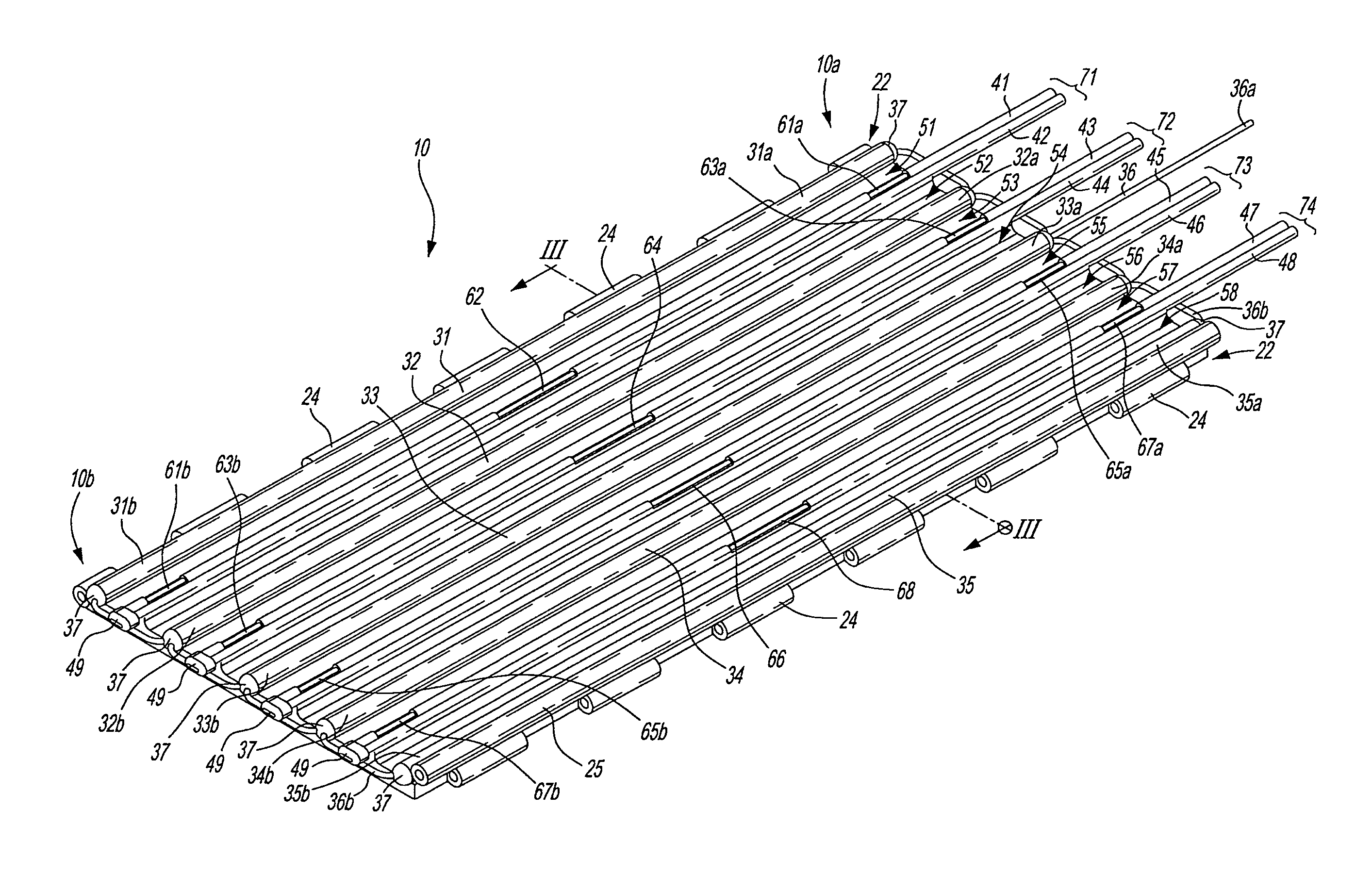
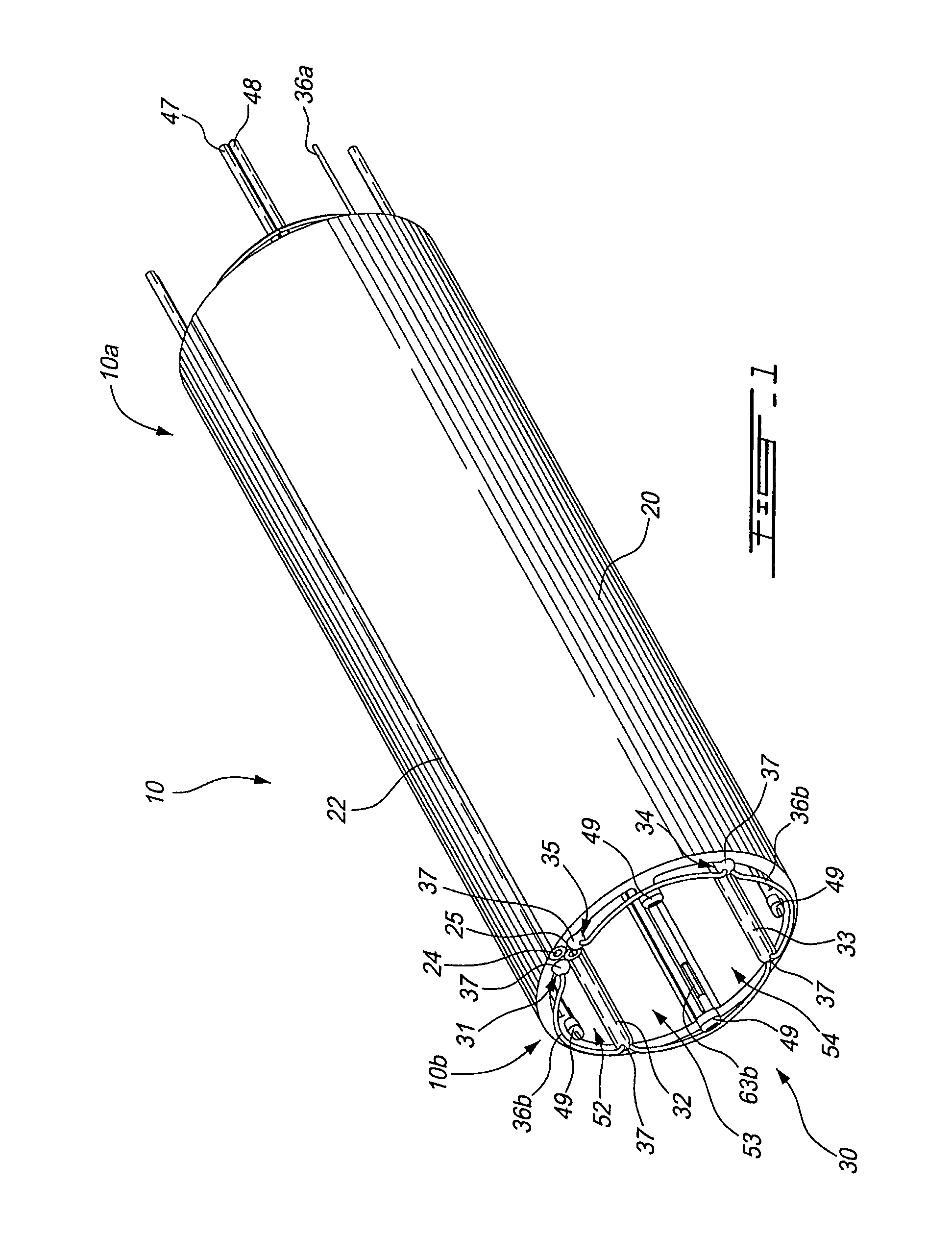
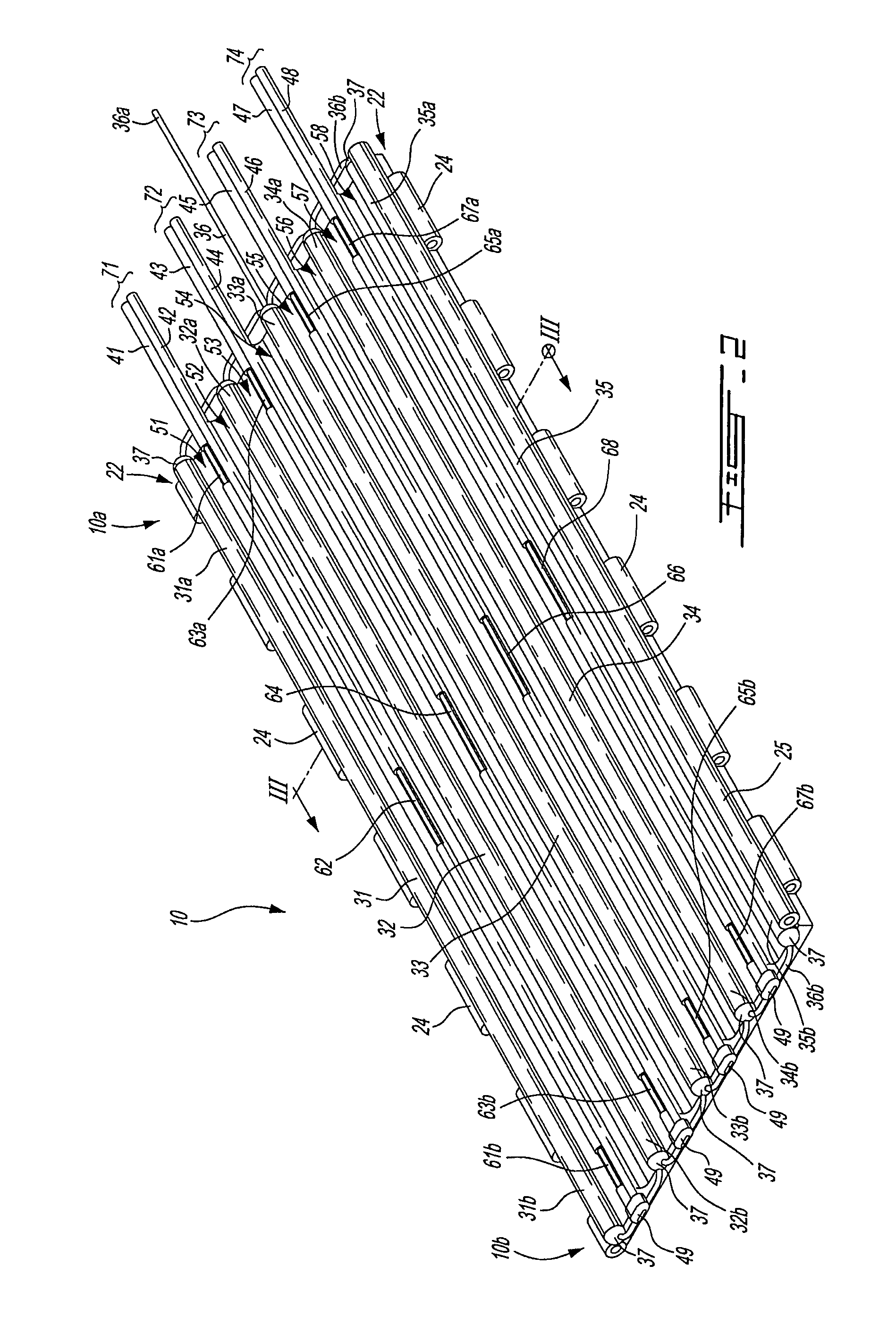
[0043]Referring to FIGS. 1 and 2, there is shown a non-limitative illustrative embodiment of a nerve cuff 10 in a closed configuration (FIG. 1) and in an open configuration (FIG. 2). The nerve cuff 10 has a wall member 20 in the form of a band which has a generally tubular configuration when in a closed configuration, as shown in FIG. 1. This wall band member or wall member 20 defines a lumen 30, when it is in the closed configuration, which is sized to receive a nerve or other bodily tissue. The surface of the wall band member 20 which defines t...


PUM

PropertyMeasurementUnit
internal diametersaaaaaaaaaa
lengthaaaaaaaaaa
timeaaaaaaaaaa

Abstract

A nerve cuff comprising a wall band member having an inner surface defining a lumen when the wall band member is in a closed configuration for receiving a nerve therethrough. At least one longitudinal and contiguous conductor extends within the lumen. The conductor is insulated and has at least one exposed portion thereby providing an electrode. When mounting the nerve cuff to a nerve, each electrode is in electrical communication with the nerve. A multi-channel nerve cuff further comprises a plurality of longitudinal ridges formed on the inner surface with each adjacent pair of ridges defining a longitudinal chamber. Each chamber comprises a respective conductor extending therein. When mounting the multi-channel nerve cuff to the nerve, the ridges abut the nerve providing for each chamber to isolate respective longitudinal portions of the nerve. A method and an apparatus for manufacturing such nerve cuffs are also disclosed.

Description

CROSS-REFERENCE TO RELATED APPLICATIONS[0001]The present applications requests priority on U.S. Provisional Application Ser. No. 60 / 810,130 which was filed on Jun. 2, 2006 and which is incorporated herein by reference in its entirety.FIELD OF THE INVENTION[0002]The present invention relates to a nerve cuff for stimulating and monitoring electrical activity in nerve tissues in human beings and other creatures possessing a nervous system. The present invention also relates to method and apparatus for manufacturing a nerve cuff.BACKGROUND OF THE INVENTION[0003]Various types of cuff transducers intended for use as electrical or chemical interfaces with neural tissue have been described in the literature. These nerve cuffs typically have a tubular biocompatible dielectric material wall. In nerve cuffs designed to provide an electrical interface to tissues inside the nerve cuff, the inside of the nerve cuff wall supports one or more metal electrodes. Leads from the electrodes extend throu...

Claims


Application Information

Patent Timeline
Patent Type & Authority Patents(United States)
IPC IPC(8): A61N1/00
CPCA61N1/0556B29C39/10Y10T29/49117B29C45/14426
Inventor HOFFER, JOAQUIN ANDRESIMBEAU, MARC-OLIVIERVALLIERES, JEAN-MARTIN
Owner 4491343 CANADA
Learn More