Method of making a nerve cuff

Inactive Publication Date: 2007-09-11
ADVANCED NEUROMODULATION SYST INC
View PDF2 Cites 2 Cited by
  • Summary
  • Abstract
  • Description
  • Claims
  • Application Information

AI Technical Summary

Problems solved by technology

The production of nerve cuffs has been problematic as the fine scale of the needed features

Method used


Image

  • Method of making a nerve cuff
  • Method of making a nerve cuff
  • Method of making a nerve cuff

Examples


Embodiment Construction

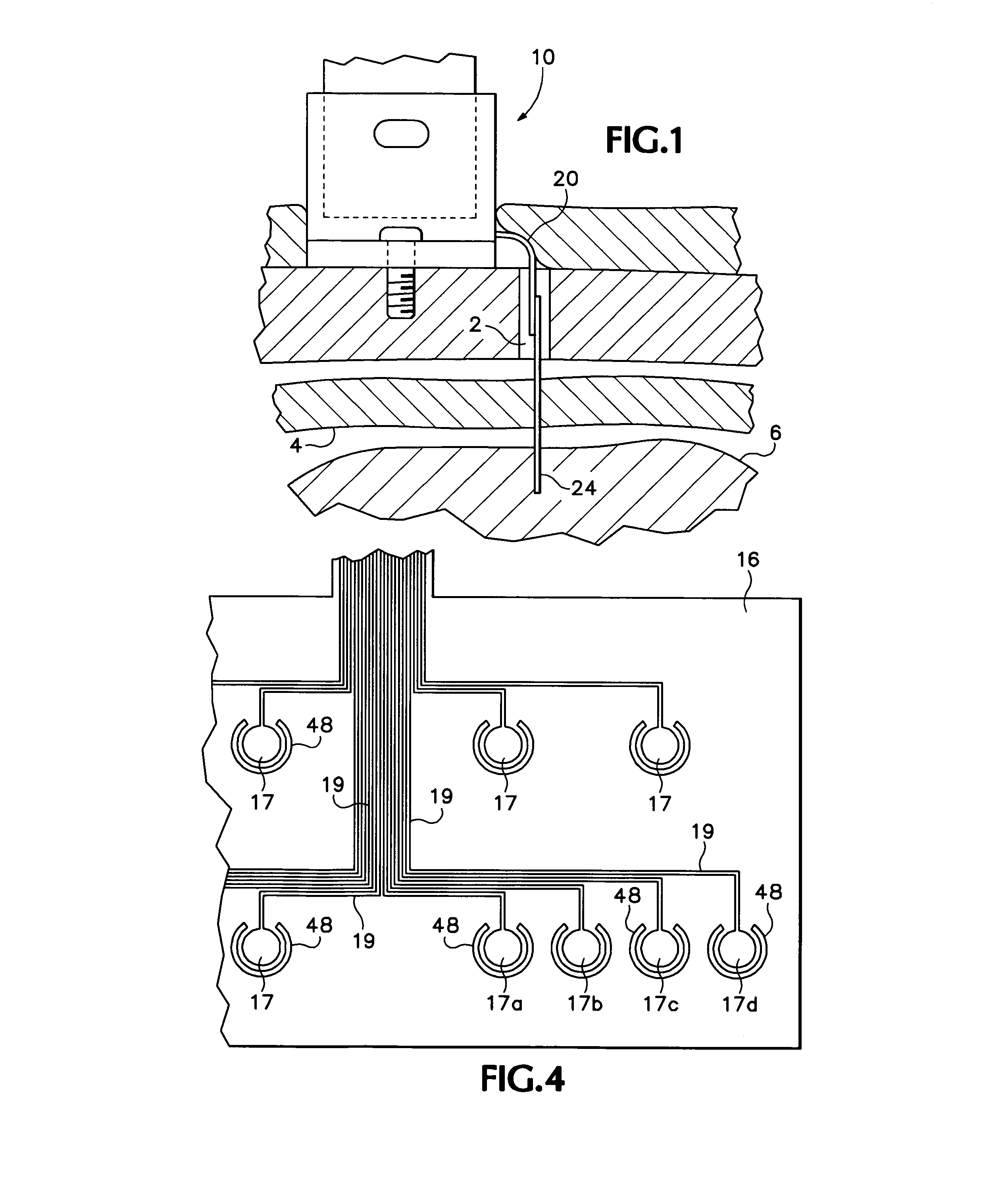
[0019]Referring to FIG. 1, a percutaneous connector 10 is screwed into the skull 1 and is connected, by way of a multi-conductor microcable 20, to a brain probe 24 that passes through an aperture 2 in the skull, through the dura 4 (and into the brain 6), for measuring brain activity at a specific set of points.

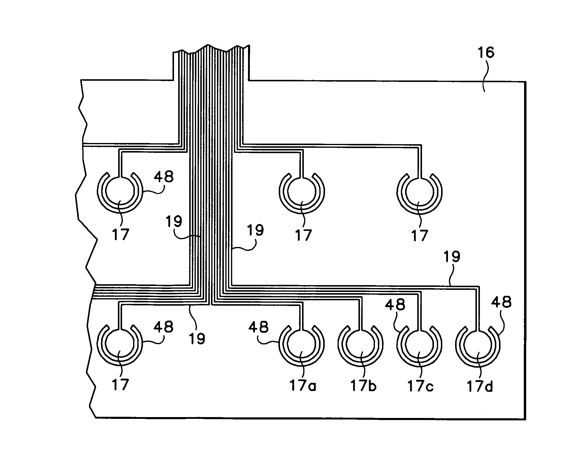
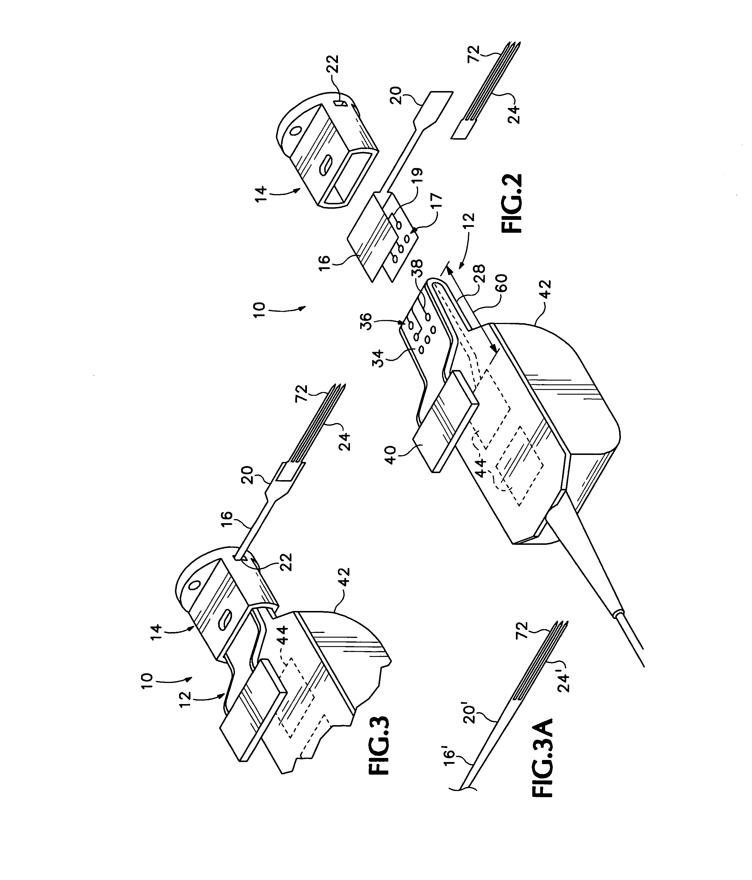
[0020]Referring to FIGS. 2, 3 and 3A a percutaneous connector 10 according to the present invention includes a male-half 12, a female-half bracket 14 and a female-half flex circuit (or flexible polymer) connective assembly 16 bearing a set of contacts 17 and conductive traces 19. A multi-conductor microcable 20 forms a portion of assembly 16 and is threaded through an aperture 22 in bracket 14. The microcable 20 attaches to and extends traces 19 to brain probe 24. As shown in FIG. 3a in an alternative embodiment, a connective assembly 16′ includes a microcable 20′ that includes a brain probe 24′ as a unitary part of its construction. In this embodiment microcable does not wide...


PUM

PropertyMeasurementUnit
Lengthaaaaaaaaaa
Lengthaaaaaaaaaa
Flexibilityaaaaaaaaaa

Abstract

A method of producing an electrode brain probe assembly, using a flexible substrate comprising a polymeric layer bearing a conductive material coating. Photolithography and electroplating are used to form a set of contacts and conductors on the polymeric layer of the flexible substrate. Also, the flexible substrate is shaped to have a distal end and to be at least 5 mm long, but less than 5 mm wide and less than 1 mm thick.

Description

RELATED PATENT APPLICATIONS[0001]The present application is a continuation-in-part of application Ser. No. 10 / 822,491, filed Apr. 12, 2004, now U.S. Pat. No. 6,973,342, which is a continuation of application Ser. No. 10 / 320,072, filed Dec. 16, 2002, now U.S. Pat. No. 6,719,582 which is a continuation-in-part of application Ser. No. 09 / 653,489, filed Aug. 31, 2000, now U.S. Pat. No. 6,495,020, which is, in turn, a divisional of application Ser. No. 09 / 518,006, filed Mar. 2, 2000, now U.S. Pat. No. 6,368,147 issued Jun. 25, 2002.STATEMENT OF GOVERNMENT SUPPORT[0002]This invention was made with government support under 2R44NS33427 awarded by the SBIR. The government has certain rights in the invention.BACKGROUND OF THE INVENTION[0003]The present invention is a method of making a flexible brain probe assembly.[0004]A nerve cuff is a device for wrapping about a nerve to electrically stimulate and / or receive electric signals from the nerve. The production of nerve cuffs has been problemat...

Claims


Application Information

Patent Timeline
IPC IPC(8): H01R43/00
CPCA61B5/04001A61N1/05H05K1/118A61N1/0556A61B2562/125A61B2562/227A61N1/0539Y10T29/49117H05K3/108H05K2201/09081Y10T29/49155Y10T29/49124A61B5/4058A61B5/24
Inventor SWANSON, JOHN W.
Owner ADVANCED NEUROMODULATION SYST INC
Why Eureka
Try Eureka