Surgical needle swage tool

a swage tool and needle technology, applied in the field of surgical needle swage tools, can solve the problems of cracking, cracking, cracking, etc., and causing stress in the needle barrel and suture,

Active Publication Date: 2012-07-10
ETHICON INC
View PDF82 Cites 14 Cited by
  • Summary
  • Abstract
  • Description
  • Claims
  • Application Information

AI Technical Summary

Benefits of technology

[0005]Another embodiment of the invention relates to a method of attaching a suture to the aforementioned type of needle barrel using two compression strokes. The first compression stroke compresses the top of the needle barrel such that the suture is compressed against the inner surfaces of the bore while the bottom and sides of the needle barrel are restrained so as to protect them from becoming substantially deformed. The second compression stroke is performed so as to compress the bottom of the needle barrel such that the suture is further compressed against the inner surfaces of the bore while the sides of the needle barrel are restrained so as to protect them from becoming substantially deformed.
[0006]Yet another embodiment of the invention relates to a method of attaching a suture to the aforementioned type of needle barrel using one compression stroke. The top and bottom of the needle barrel are compressed concurrently with a flat surface of a first tool and a flat surface of a second tool, respectively, such that the suture is compressed against the inner surfaces of the bore while the sides of the needle barrel are restrained so as to protect them from becoming substantially deformed.

Problems solved by technology

While this approach provides good attachment, each hit on the barrel of the needle produces stress in the needle barrel and suture.
The materials of which the needle and suture are made inherently have some degree of malleability, but when the limit of malleability is reached, the material will fail, leading to, in the case of the needle, cracking and loss of attachment, or breakage.
Cracking is a particular problem when harder alloys are used, including advanced alloys such as 4310 SS, nickel-titanium SS, and 420 SS.
Further, needle materials have some elasticity, such that the relief of residual stress causes the needle barrel to relax over time, leading to a loss of attachment between the needle bore and the suture.

Method used


Image

  • Surgical needle swage tool
  • Surgical needle swage tool
  • Surgical needle swage tool

Examples


Embodiment Construction

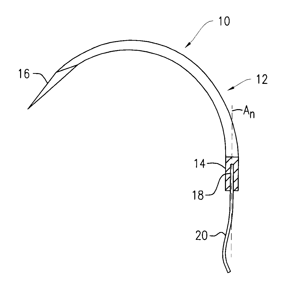
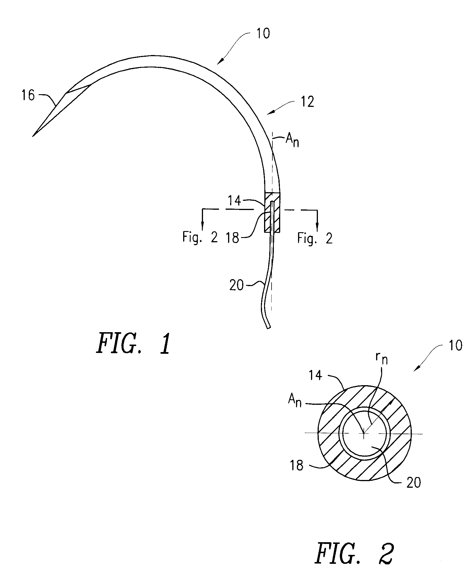
[0032]The devices and methods described herein are intended for use with a surgical needle (subsequently, “the needle”), such as the unswaged needle 10 depicted in FIGS. 1 and 2. The needle 10 may have a curved body 12 having a tubular end 14 (subsequently, “the needle barrel”) and a sharp end 16. The needle barrel 14 includes a straight bore 18 that opens outwardly (shown in FIG. 1 in a cutaway view) opposite the sharp end 16. FIG. 2 is a cross-sectional end view of the needle barrel 14, which will typically have a circular cross-section with a radius rn about a central longitudinal axis An. The needle barrel 14 can be provided with a radius rn in the range of radiuses of conventional wire sizes (e.g., about 0.003 inches to about 0.035 inches). The needle 10 may be made of any one of a number of metal alloys, including, but not limited to, 4310 SS, nickel-titanium (NiTi) SS and 420 SS, or advanced alloys, such as, tungsten-rhenium (W—Re) alloys and refractory alloys. The bore 18 is...


PUM

PropertyMeasurementUnit
sizesaaaaaaaaaa
angles a1aaaaaaaaaa
angles a1aaaaaaaaaa

Abstract

In a method of attaching a suture to a needle barrel, a first compression stroke compresses the radially-defined top of the barrel against a suture in the bore of the barrel while restraining the bottom and sides of the barrel against deformation. A second compression stroke compresses the bottom of the barrel against the suture while restraining the sides against deformation. In another method, the top and bottom are compressed concurrently while the sides are restrained against deformation. An apparatus for attaching a suture to a needle barrel includes two die sets, each including a die with a groove therein. In one die set, the groove protects the bottom and sides of the barrel from deformation while the top is compressed. In the other die set, the groove protects the sides of the barrel from deformation while the bottom is compressed.

Description

FIELD OF INVENTION[0001]The present invention relates to apparatus and methods for attaching needles to sutures, such as for making armed sutures for surgical applications, and, more particularly, to apparatus and methods for attaching surgical needles to sutures using a swaging process.BACKGROUND OF INVENTION[0002]Various methods for swaging needles to sutures are known. In a surgical needle of a well-known type, the free end of a suture is inserted into an axial bore within a blunt end of the needle (the “needle barrel”), and held in that position while a swage die impinges upon the outer surface of the needle barrel, thereby compressing a portion of the bore onto the suture. The compressed portion of the bore grasps the suture by mechanical interference and by surface contact (friction). The swaging process is conducted so as to create an attachment between the needle barrel and suture that meets or exceeds the attachment (or “pull-out”) strength requirements of standards such as...

Claims


Application Information

Patent Timeline
Patent Type & Authority Patents(United States)
IPC IPC(8): B21D39/00B21G1/12
CPCA61B17/06004Y10T29/49925A61B2017/06028A61B2017/00526
Inventor STAMETZ, JERRYPRICE, JOHNREYNOLDS, EUGENEBARSCH, KENNETH
Owner ETHICON INC
Why Eureka
Try Eureka