Infusion device

Inactive Publication Date: 2012-07-17
MEDTRONIC MIMIMED INC
View PDF119 Cites 11 Cited by
  • Summary
  • Abstract
  • Description
  • Claims
  • Application Information

AI Technical Summary

Problems solved by technology

Each one of these insulin delivery options has advantages, disadvantages and limitations with respect to factors such as convenience, cost, effort, safety, reliability and pain.
However, direct injection with a syringe sometimes necessitates multiple injections during the course of a day.
For other diabetics, multiple direct injections per day and bruises at the injection site become too much to tolerate.
Regardless of the particular reason or reasons, there are a large number of diabetics who cannot bring themselves to inject their insulin directly with a needle or who lose their ability to tolerate direct injections with a syringe.
These diabetics often under-medicate themselves, endangering their physical health and mental well being.
Although a needle is not used, jet spray injection exhibits a similar level of pain and bruising associated with its use as do direct injections with a syringe.
However, because the infusion device may remain in place for an extended period of time (e.g., typically up to 3 days or more), the diabetic need only deal with one injection type needle over 3 or more days, rather than multiple times per day.
One disadvantage is that the precise measurement of insulin and the security of m

Method used


Image

  • Infusion device
  • Infusion device
  • Infusion device

Examples


Example

[0033]FIG. 3 depicts an infusion device 100 in accordance with a second embodiment of the disclosures made herein. The infusion device 100 is similar in structure to the infusion device 10 depicted in FIGS. 1 and 2. Structural elements and features of the infusion device 100 and the infusion device 10 (depicted in FIGS. 1 and 2) are similarly denoted. For example, the body of the infusion device 100 is denoted as 112, whereas the body of the infusion device 10 is denoted as 12. Such similar elements and features are denoted for clarity in FIG. 3, but may not be discussed in specific detail in reference to FIG. 3.

[0034]The infusion device 100 includes a body 112, a self-sealing member 116 mounted on an accessible surface 118 of the body 112 and a single outlet port 124 that is offset from an engagement surface 122 of the body 112. The self-sealing member 116 forms a septum extending across the medication delivery channel 126. The septum limits contaminants entering the medication del...

Example

[0036]FIG. 4 depicts an infusion device 200 in accordance with a third embodiment of the disclosures made herein. The infusion device 200 is similar in structure to the infusion device 10 depicted in FIGS. 1 and 2. Structural elements and features of the infusion device 200 and the infusion device 10 (depicted in FIGS. 1 and 2) are similarly denoted. For example, the body of the infusion device 200 is denoted as 212, whereas the body of the infusion device 10 is denoted as 12. Such similar elements and features are denoted in FIG. 4, but may not be discussed in specific detail in reference to FIG. 4.

[0037]The infusion device 200 includes a body 212 and a self-sealing member 216. The self-sealing member 216 is mounted on the body 212 adjacent to an engagement surface 222 of the body 212 and at least partially within the medication delivery channel 226. The self-sealing member 216 forms a septum extending across the medication delivery channel 226 adjacent to a single outlet port 224 ...

Example

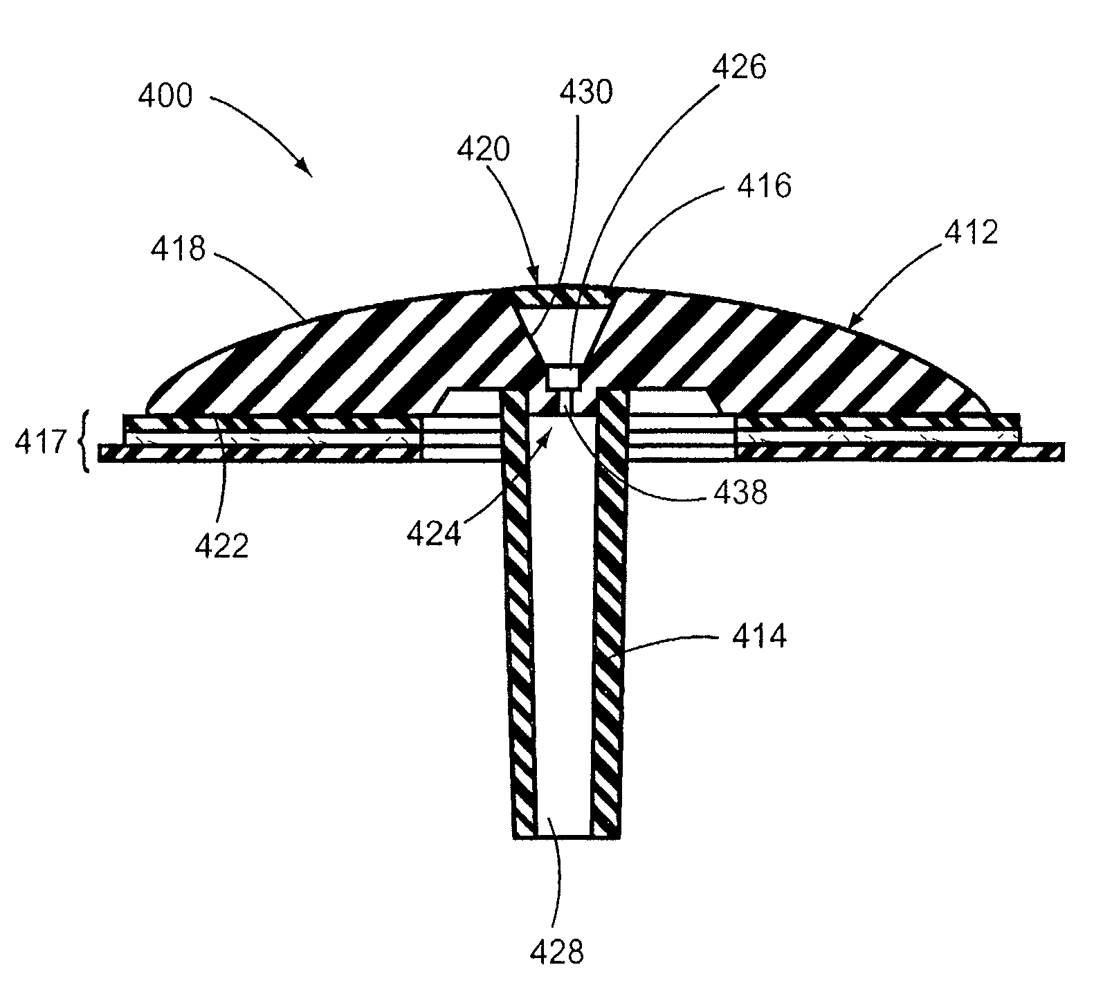
[0038]FIG. 5 depicts an infusion device 300 in accordance with a fourth embodiment of the disclosures made herein. The infusion device 300 is similar in structure to the infusion device 10 depicted in FIGS. 1 and 2. Structural elements and features of the infusion device 300 and the infusion device 10 (depicted in FIGS. 1 and 2) are similarly denoted. For example, the body of the infusion device 300 is denoted as 312, whereas the body of the infusion device 10 is denoted as 12. Such similar elements and features are denoted in FIG. 5, but may not be discussed in specific detail in reference to FIG. 5.

[0039]The infusion device 300 includes a body 312, a first self-sealing member 316 mounted on the body 312 adjacent to an accessible surface 318 of the body 312 and a second self-sealing member 319 mounted on the body 312 adjacent to an engagement surface 322 of the body 312. The first self-sealing member 316 forms a septum extending across the medication delivery channel 326 adjacent t...


PUM


Abstract

The disclosures made herein relate to an infusion device specifically adapted for syringe injections. In one embodiment of the disclosures made herein, an infusion device comprises a body including an accessible surface having a single inlet port therein, an engagement surface having a single outlet port therein, a medication delivery channel extending between the single inlet port and the single outlet port, and an identification feature on the accessible surface of the body adjacent to the single inlet port. The single inlet port of the medication delivery channel is tapered thereby forming a funnel-shaped entry into the medication delivery channel. A cannula is coupled to the body at the single outlet port and is adapted for receiving medication from the single outlet port and transmitting the medication therethrough.

Description

CROSS-REFERENCE TO RELATED APPLICATION[0001]This is a continuation of application Ser. No. 10 / 188,591, filed Jul. 2, 2002, now U.S. Pat. No. 7,338,465, issued Mar. 4, 2008, which is incorporated by reference without disclaimer.FIELD OF THE DISCLOSURE[0002]The disclosures herein relate generally to infusion devices and method, and more particularly to a subcutaneous infusion device specifically adapted for receiving therapeutic substances injected with a syringe.BACKGROUND[0003]Presently, the delivery options available to insulin dependent diabetics for insulin delivery include direct injections with a syringe, continuous-delivery with an insulin pump and injections with a jet-spray. Each one of these insulin delivery options has advantages, disadvantages and limitations with respect to factors such as convenience, cost, effort, safety, reliability and pain. Accordingly, selection of an acceptable delivery option by a diabetic will depend on the advantages of a selected insulin deliv...

Claims


Application Information

Patent Timeline
IPC IPC(8): A61M5/00A61M5/158A61M1/00
CPCA61M39/0247A61M5/162A61M39/04A61M2039/0294A61M2039/027
Inventor PATTON, CATHERINE C.
Owner MEDTRONIC MIMIMED INC
Why Eureka
Try Eureka