Vacuum switch and vacuum switchgear

a vacuum switch and switchgear technology, applied in the direction of air-break switch, high-tension/heavy-dress switch, electrical apparatus, etc., can solve problems such as dielectric breakdown, and achieve the effect of improving isolation reliability

Inactive Publication Date: 2012-07-24
HITACHI LTD
View PDF9 Cites 4 Cited by
  • Summary
  • Abstract
  • Description
  • Claims
  • Application Information

AI Technical Summary

Benefits of technology

[0012]Accordingly, an object of the present invention is to provide a vacuum switch and a vacuum switchgear that prevents an electric field from concentrating on the angular part at each end of the insulating cylinder to suppress dielectric breakdown.
[0016]According to the vacuum switch and the vacuum switchgear of the present invention, the angular part at the end of the insulating cylinder can be covered, so an electric field is not concentrated on this part, dielectric breakdown is suppressed, and thereby isolation reliability is improved.

Problems solved by technology

However, the structure disclosed in Patent Document 1 is problematic in that because the doughnut-shaped electric field relieving shield disposed at each end of the insulating cylinder has a doughnut shape formed by connecting both ends of a single spiral spring, the angular part at the end of the insulating cylinder, at which an electric field is most concentrated, cannot be covered and thereby an electric field is concentrated on the angular part at the end of the insulating cylinder, which may lead to dielectric breakdown.

Method used


Image

  • Vacuum switch and vacuum switchgear
  • Vacuum switch and vacuum switchgear
  • Vacuum switch and vacuum switchgear

Examples


first embodiment

[0037]a vacuum switch according to the present invention will be described using FIGS. 1 to 5.

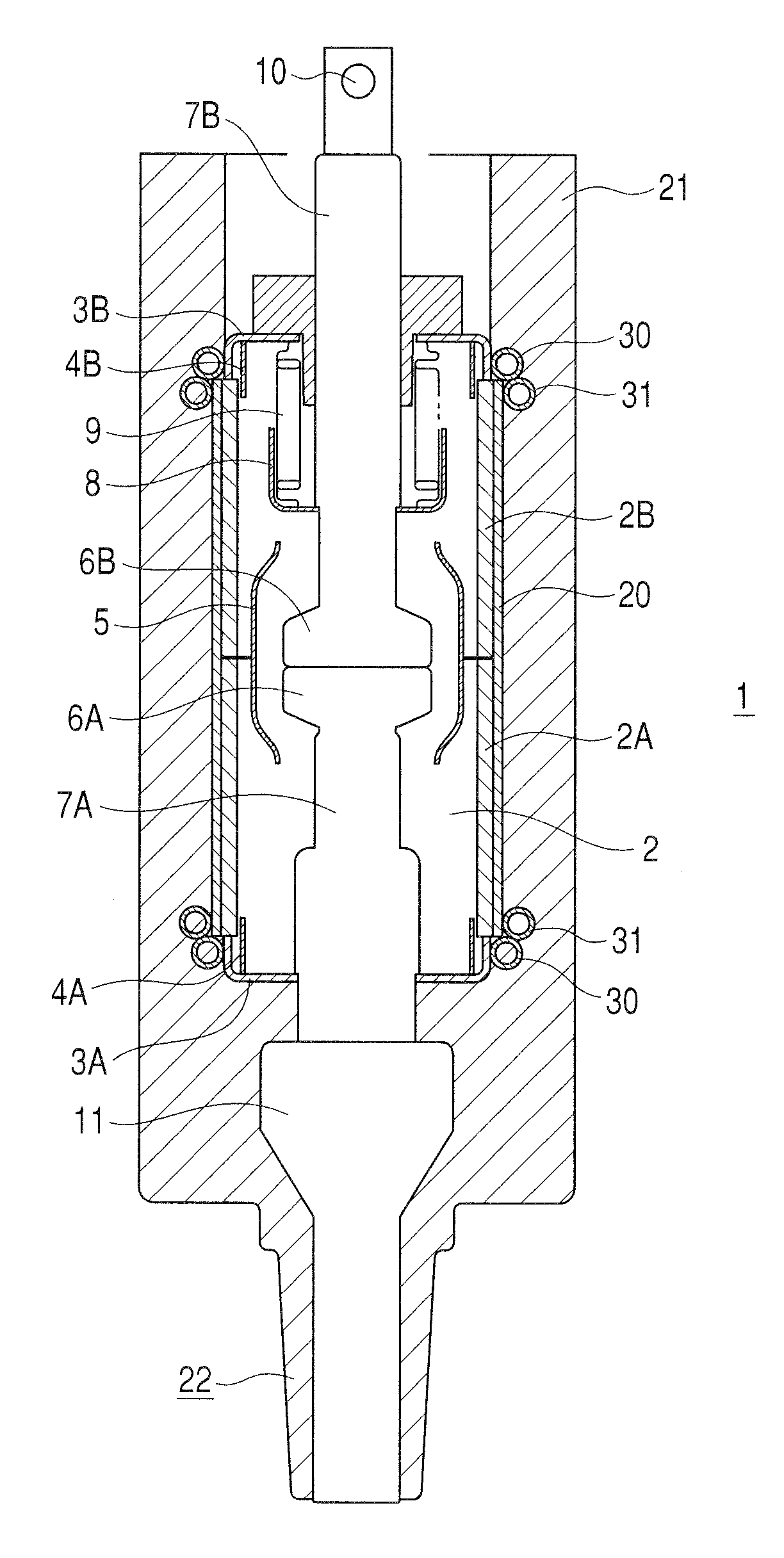
[0038]As shown in FIG. 1, the vacuum switch 1 in the first embodiment of the present invention substantially comprises a vacuum chamber 2, a fixed electrode 6A and a movable electrode 6B disposed in the vacuum chamber 2, and a solid isolation resin 21 covering the circumference of the vacuum chamber 2.

[0039]The vacuum chamber 2 comprises a fixed-side ceramic insulating cylinder 2A, a movable-side ceramic insulating cylinder 2B linked to the fixed-side ceramic insulating cylinder 2A, a fixed-side end plate 3A linked to a fixed end of the fixed-side ceramic insulating cylinder 2A in its axial direction, the fixed-side end plate 3A being metallic and thinner than the insulating cylinders 2A and 2B, and a movable-side end plate 3B linked to a movable end of the movable-side ceramic insulating cylinder 2B, the movable-side end plate 3B being metallic; the interior of the vacuum chamber 2 is main...


PUM


Abstract

A vacuum switch has a fixed electrode, a movable electrode facing the fixed electrode, an insulating cylinder, end plates covering both axial ends of the insulating cylinder, a vacuum chamber internally accommodating the fixed electrode and the movable electrode, and a solid isolation resin molded on the outside of the vacuum chamber, first coil springs, each of which is disposed around the outer circumference of one end plate while touching the end plate and an end face of the insulating cylinder, and second coil springs, each of which is united to one of the first springs and disposed around the outer circumference of the insulating cylinder so as to cover the angular part of the end face of the insulating cylinder, and the end plates, the end faces of the insulating cylinder, and the first and second coil springs are electrically connected.

Description

CLAIM OF PRIORITY[0001]The present application claims priority from Japanese patent application serial No. 2008-169775, filed on Jun. 30, 2008, and Japanese patent application serial No. 2008-202605, filed on Aug. 6, 2008, the contents of which are hereby incorporated by reference into this application.BACKGROUND OF THE INVENTION[0002]1. Field of the Invention[0003]The present invention relates to a vacuum switch and a vacuum switchgear, and more particularly relates to a vacuum switch and a vacuum switchgear that are suitable when the circumference of a vacuum chamber accommodating the switch unit is isolation-molded.[0004]2. Description of Related Art[0005]A vacuum switch is a switch that utilizing high-vacuum isolation performance; a compact, SF6 gasless switch can be achieved.[0006]Some vacuum switches have isolation performance improved by not only vacuum insulation but also by the use of a double layered isolating structure in which the circumference of the switch chamber is c...

Claims


Application Information

Patent Timeline
Patent Type & Authority Patents(United States)
IPC IPC(8): H01H33/66
CPCH01H33/66261H01H2033/66284H01H2033/6623H01H33/66H01H33/60
Inventor TSUCHIYA, KENJISATO, TAKASHIYAMAZAKI, MIKIKOBAYASHI, MASATOOZAWA, HIROYUKI
Owner HITACHI LTD
Why Eureka
Try Eureka