Combined pumping and separating machine for the oil circuit of a turbojet

a turbojet and oil circuit technology, applied in the direction of engine lubrication, foam dispersion/prevention, non-positive displacement pumps, etc., can solve the problems of large variation in strength of two-phase mixture, system problems, and general uncoupling of the separation system from the pumping function, so as to improve the overall yield of oil circuit, improve the quality of air/oil separation, and reduce oil consumption

Active Publication Date: 2012-07-31
TECHSPACE AERO
View PDF10 Cites 22 Cited by
  • Summary
  • Abstract
  • Description
  • Claims
  • Application Information

AI Technical Summary

Problems solved by technology

Moreover, the separation system is generally uncoupled from the pumping function.
So, in the field of the lubrication of aircraft engines, these systems pose problems as a result of their bulk, their weight and more indirectly as a result of their complex installation.
The system described in this document is not well suited to major variations in strength of the two-phase mixture as found in turbine engines.
The machines proposed in the state of the art are therefore not efficient across the entire range of proportions of liquid / gas encountered with the two-phase oil / air mixture in the field of a flying aircraft engine.
In particular, a skimming machine would be saturated and would not work well in the case of the flight of a manoeuvring airplane.
This lack of performance with the discarded mixture would lead, when using similar systems, to an oversized equipment and a lack of compactness, whereas this latter aspect is important in onboard aircraft equipment.

Method used


Image

  • Combined pumping and separating machine for the oil circuit of a turbojet
  • Combined pumping and separating machine for the oil circuit of a turbojet
  • Combined pumping and separating machine for the oil circuit of a turbojet

Examples


Embodiment Construction

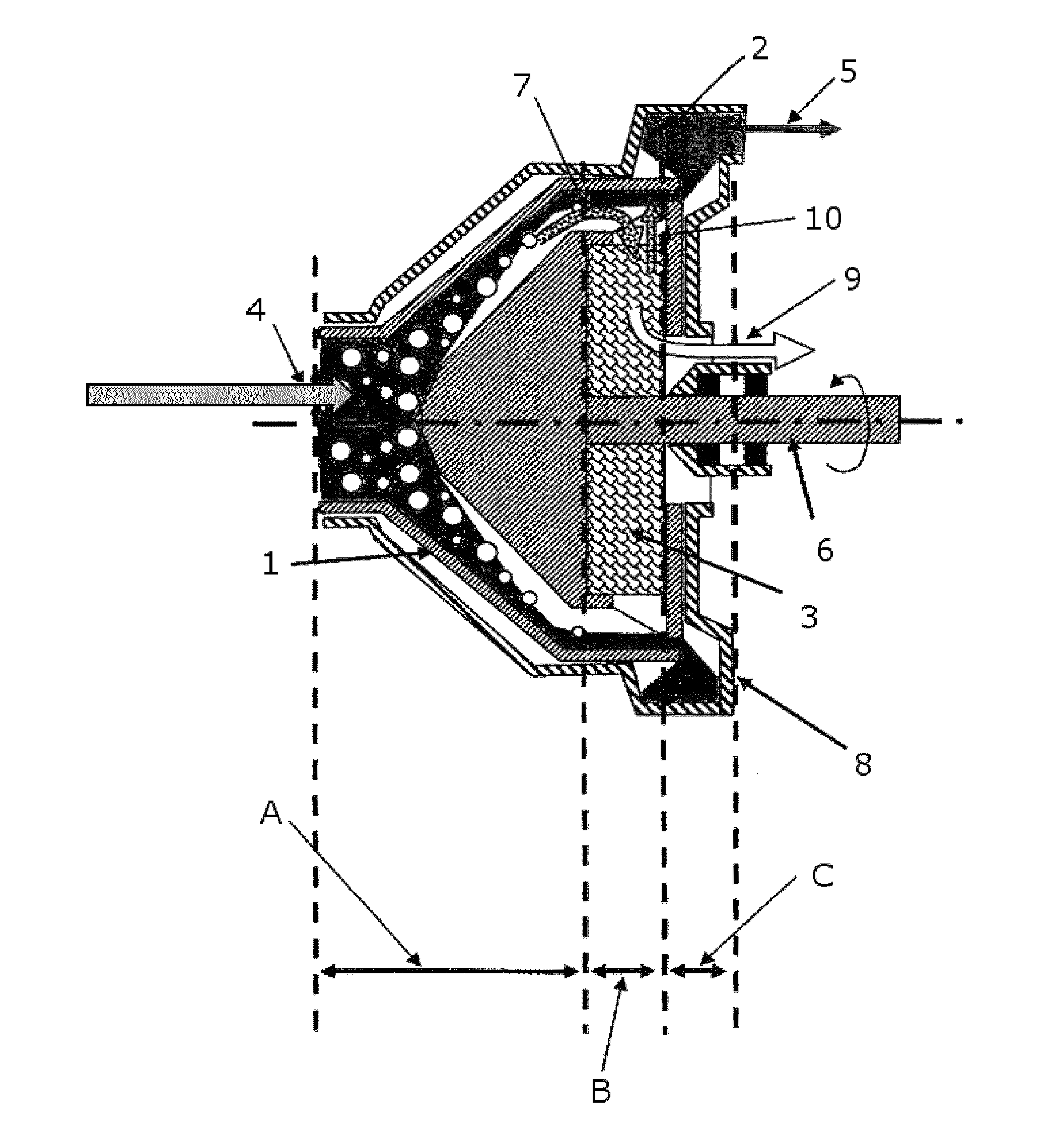
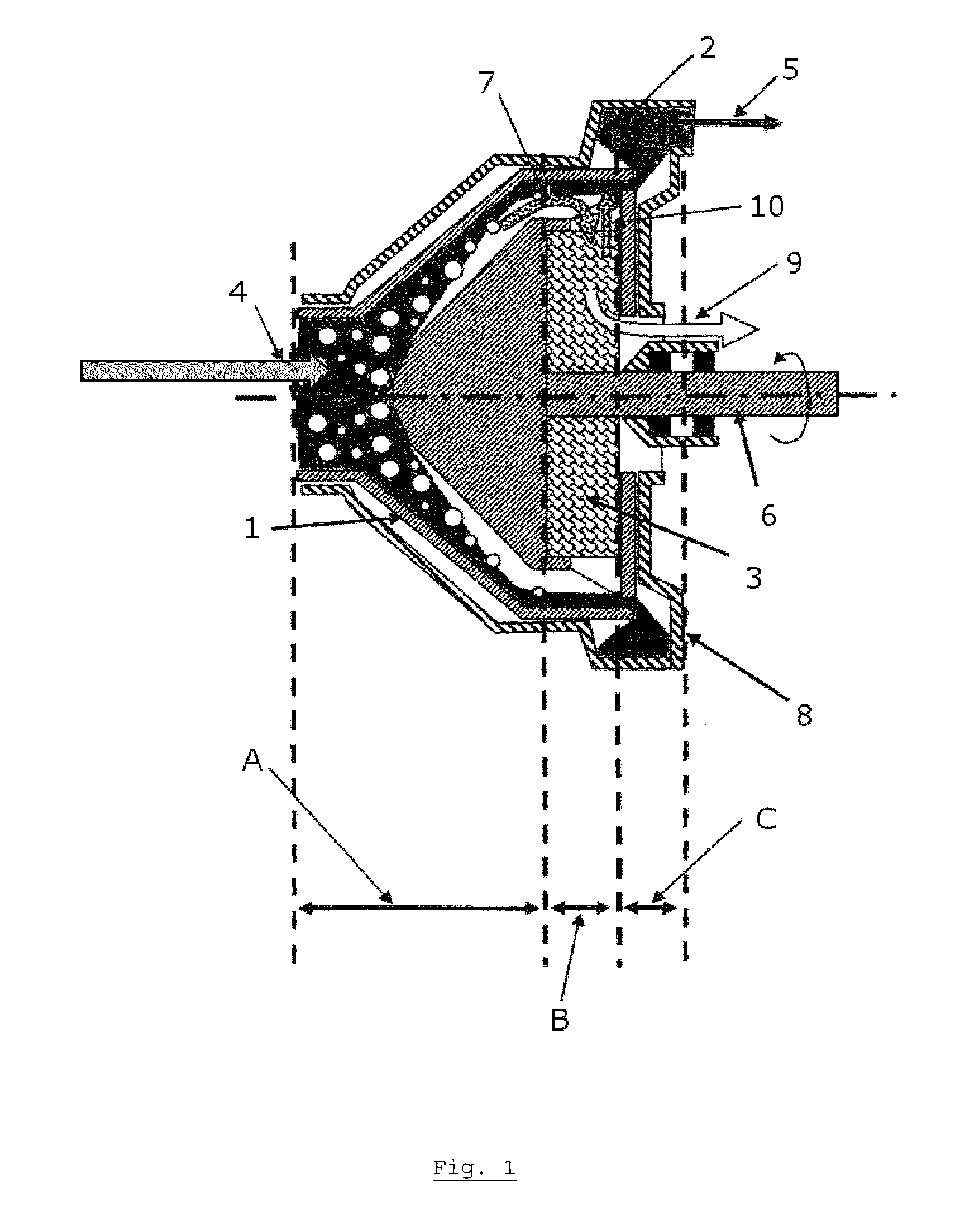
[0053]The present invention discloses a machine in which the various above-mentioned functions are separately performed thanks to the use of a particular staging arrangement such as for example (but not restricted to): suction of the liquid / gas mixture, pressurisation, degassing of the mixture, removal of oil from the gas extracted in the previous stage, etc.

[0054]According to a particular embodiment, the present invention discloses in particular a machine such as that shown in FIG. 1, comprising three stages and four zones intended to separately perform the four above-mentioned functions:[0055]a first stage A corresponding to an axial-centrifugal pumping zone for the air / oil mixture ensuring the suction function with partial separation of the two fluids, called an “inductor”;[0056]a second rotating separation stage B, subdivided into two concentric zones, a first buffer zone which is essentially ring-shaped on the outer periphery of the second stage B, which allow to deaerate the o...


PUM

PropertyMeasurementUnit
pressureaaaaaaaaaa
internal diameteraaaaaaaaaa
compositionaaaaaaaaaa

Abstract

A combined machine for pumping and separating into two distinct and purified phases a two-phase liquid / gas mixture or fluid, is provided. A first stage of the combined machine is equipped with an intake for the two-phase fluid, in which the two-phase fluid is sucked, pumped and partially separated into two distinct phases. One phase is mainly liquid and the other phase is mainly gaseous. A second stage of the combined machine includes two zones, which includes a first zone and a second zone. In the first zone, the mainly liquid phase extracted from the first stage is degassed. In the second zone, the mainly gaseous phase extracted from the first stage is dried. In a third stage of the combined machine, the degassed liquid is forced back and pressurized.

Description

CROSS-REFERENCE TO RELATED PATENT APPLICATIONS[0001]This patent application claims the benefit of European Application No. 08172593.9 filed Dec. 22, 2008, the entire teachings and disclosure of which are incorporated herein by reference thereto.FIELD OF THE INVENTION[0002]The present invention relates to a centrifugal machine that can perform, in full or in part, the following four functions:[0003]Suction,[0004]oil removal or, more generally, drying,[0005]deaeration or, more generally, degassing, and[0006]forcing back a gas / liquid mixture.The mixture comprises for example air and oil, or more generally a light fluid and a heavy fluid.[0007]The machine as in the invention must be able to manage the variations in strength of the mixture upon entry and to allow the acceptance of a mixture of anything from a pure gas to a pure liquid, and must be able to produce the two separated phases of this mixture upon exit.[0008]The technical application field is more particularly that of the oil ...

Claims


Application Information

Patent Timeline
Patent Type & Authority Patents(United States)
IPC IPC(8): B01D19/00
CPCB01D19/0026B01D19/0052B01D19/0063F04D7/045F04D31/00
Inventor CORNET, ALBERTRAIMARCKERS, NICOLAS
Owner TECHSPACE AERO
Why Eureka
Try Eureka