Bone splitting and breaking tool

a technology of pelvic bone and tool, which is applied in the field of pelvic bone splitter or pelvic bone tool, can solve the problems of hunting knives generally ineffective for severing large bones, meat to have a strong taste or smell, and the hunter to unintentionally cut or puncture an organ

Inactive Publication Date: 2012-08-07
MOY YUEY S
View PDF13 Cites 6 Cited by
  • Summary
  • Abstract
  • Description
  • Claims
  • Application Information

AI Technical Summary

Problems solved by technology

Failure to empty the body cavity of digestive and excretory organs promptly can cause the meat to have a strong, gamey taste or smell.
While practical and convenient, hunting knives are generally ineffective for severing large bones.
The obstacle presented by the pelvic bone often causes a hunter to unintentionally cut or puncture an organ, exposing the meat to contaminants.
Each of those tools and methods has drawbacks.
Using a rock to strike a knife blade is both dangerous and difficult.
Personal injury or i

Method used


Image

  • Bone splitting and breaking tool
  • Bone splitting and breaking tool
  • Bone splitting and breaking tool

Examples


first embodiment

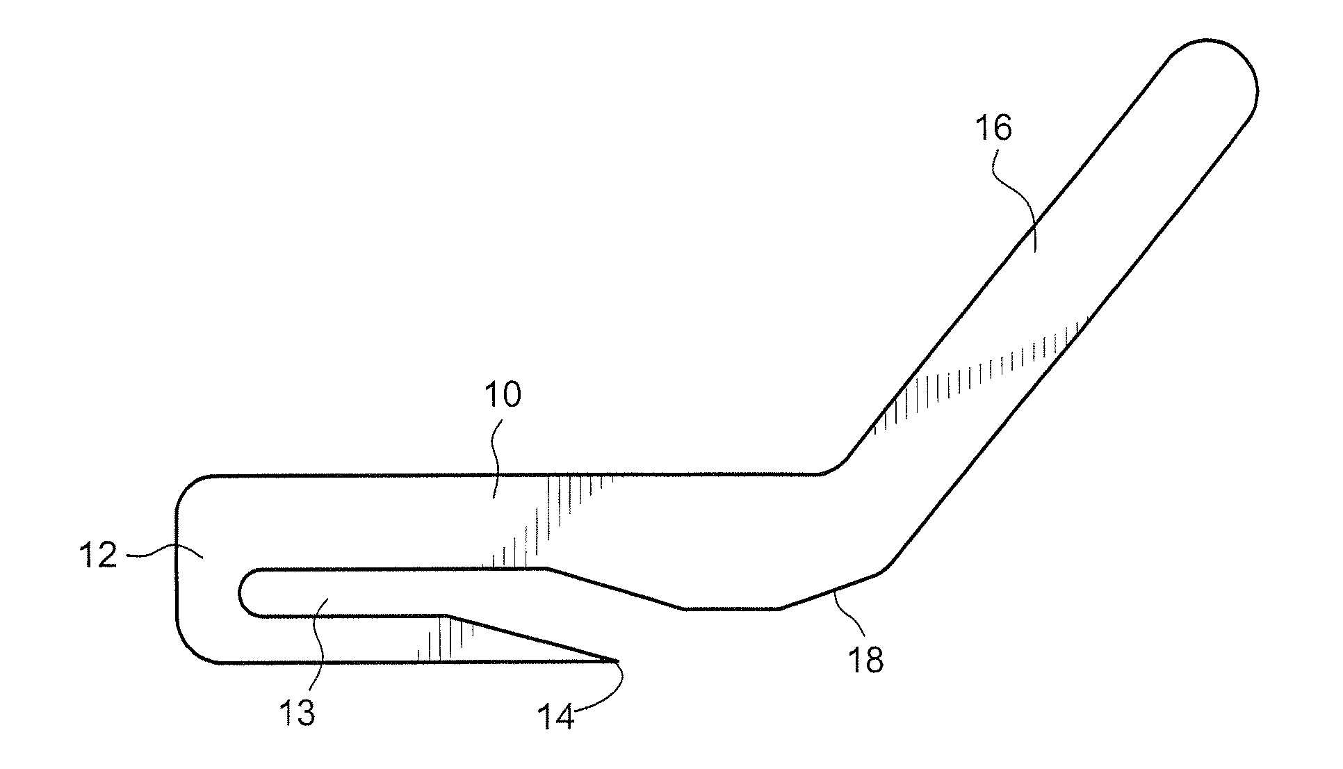
[0019]the tool is illustrated in FIG. 1. As shown therein, the tool includes a U-shaped main body 10. The two arms of the U-shaped main body 10 are joined by a front end 12, and an aperture 13 is formed between the two arms of the main body 10. A handle 16 extends away from the main body 10 at an angle.

[0020]A projection 18 is located on the rear end of one arm of the U-shaped main body 10 adjacent a location where the handle 16 joins the main body 10. A pointed tip 14 is located at the rear end of the other arm of the U-shaped main body 10.

[0021]To use the tool, the hunter would position the tool such that the pelvic bone is received in the aperture 13 between the two arms of the U-shaped main body 10. The projection 18 would bear against approximately the center of the pelvic bone of the game animal. The hunter would then push downward on the handle 16 to drive the projection 18 into the top of the pelvic bone and to thereby break the pelvic bone.

[0022]The tool can be positioned a...

second embodiment

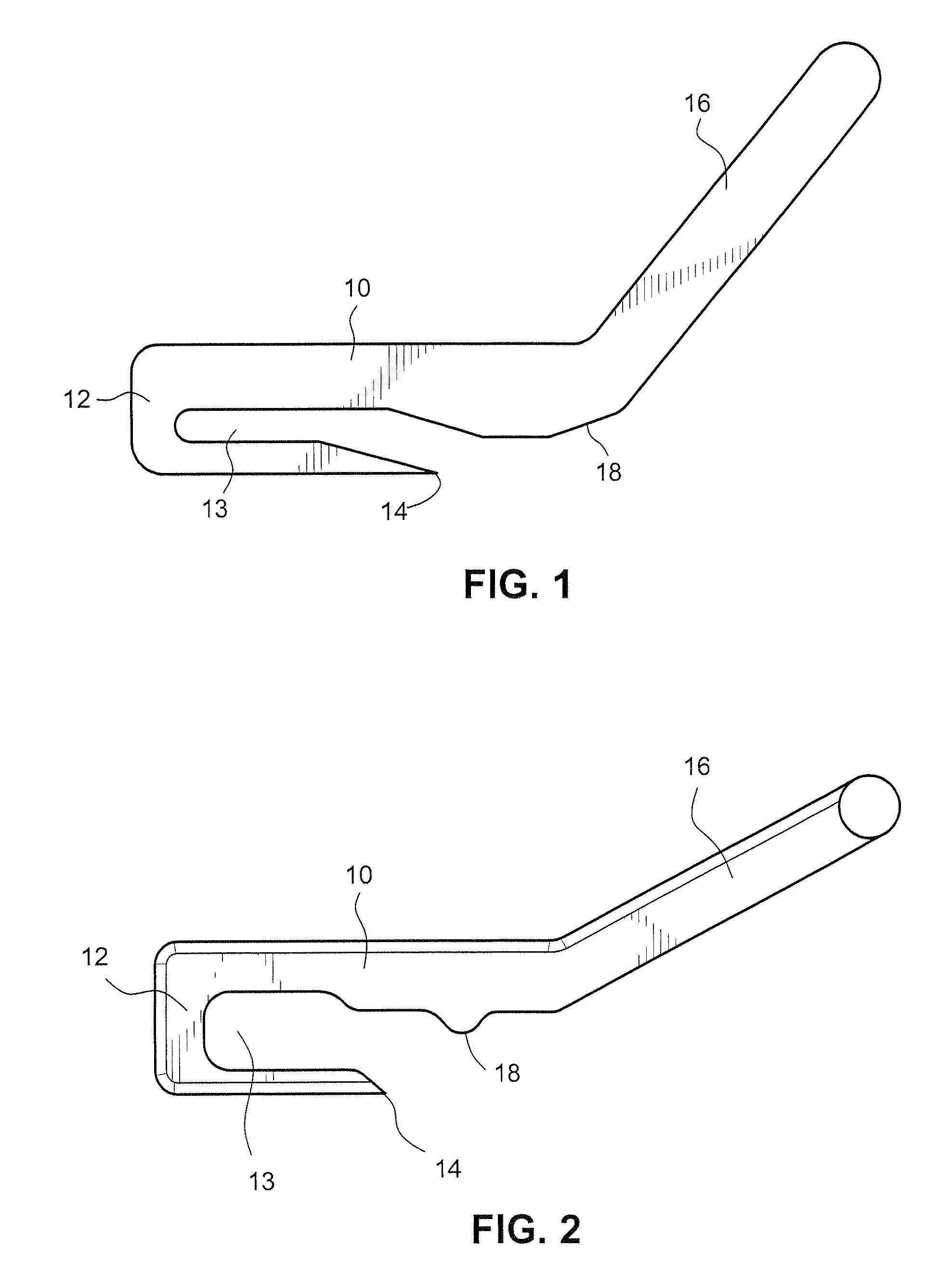
[0023]the tool is illustrated in FIG. 2. In this embodiment, the projection 18 comes to a sharper point and extends further away from the aim upon which it is formed.

third embodiment

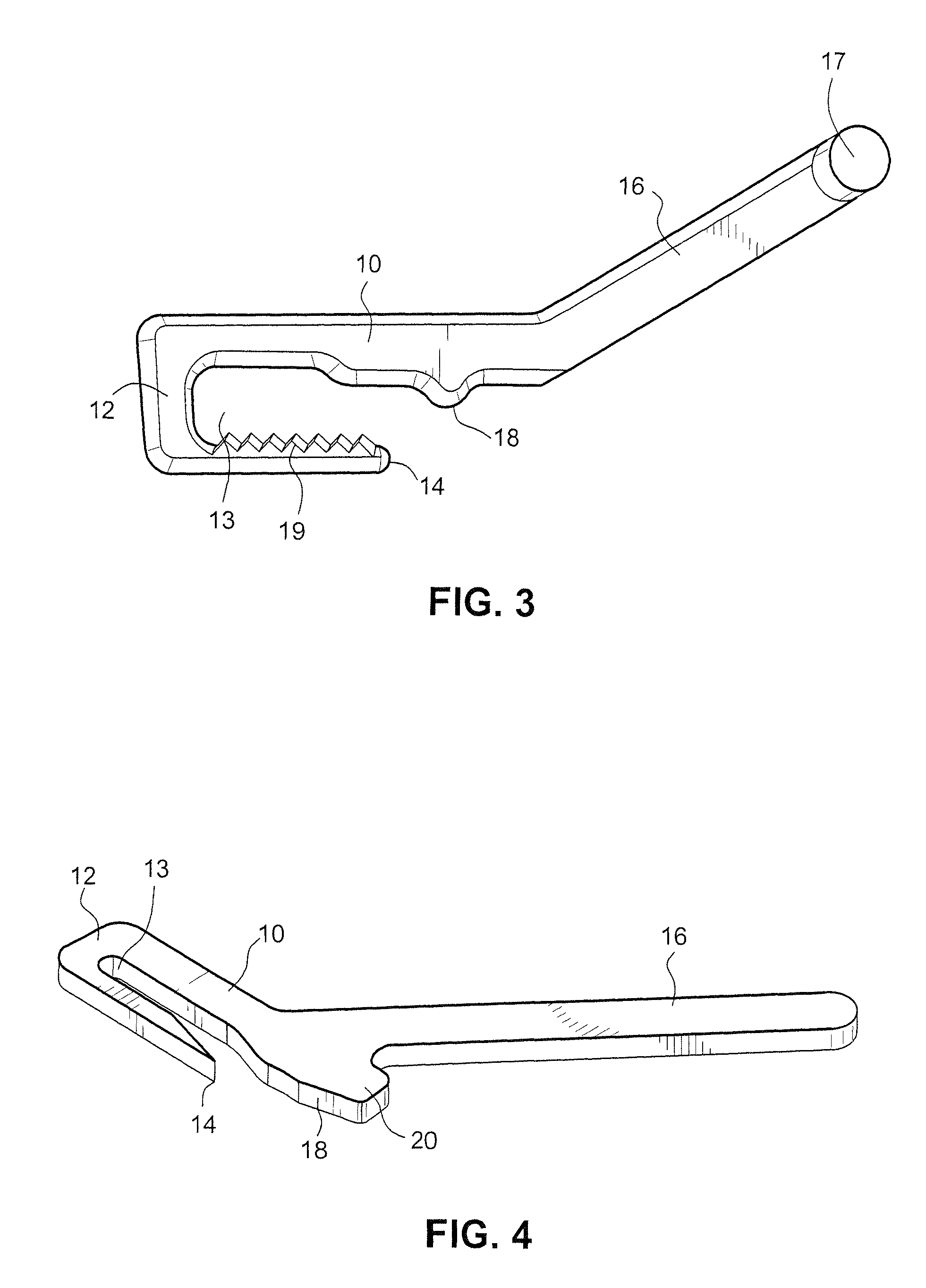
[0024]the tool is illustrated in FIG. 3. In this embodiment, serrated teeth 19 are formed on the atm of the U-shaped body 10 opposite the projection 18. The serrated teeth 19 are designed to provide a better grip so that the tool does not slip when in use. Although the embodiment illustrated in FIG. 3 shows serrated teeth 19 on the lower arm opposite the projection 18, serrated teeth could also be provided on the upper arm. The teeth could have any form other than the ones shown in FIG. 3. In addition, structures other than teeth could also be formed on the lower and / or upper arm, so long as the structures increase the ability of the tool to grip and not slip while in use. For example, a series of pointed protrusions could be provided instead of teeth.

[0025]The third embodiment also includes a projection 17 formed at the end of the handle 16. The projection 17 extends from the end of the handle 16 in a direction that is substantially perpendicular to the longitudinal axis of the han...


PUM


Abstract

A bone breaking or crushing tool for use by a hunter is designed to break the pelvic bone of a game animal. The bone breaking tool includes a U-shaped body having first and second arms joined by a front end. A handle projects at an angle from an outer side of a first arm of the U-shaped main body. A projection is formed on an inner side of the first arm of the U-shaped main body. The bone breaking tool is configured so that the first and second arms of the U-shaped main body can be slid around either side of a portion of the pelvic bone of a game animal. A hunter can then apply a force to an end of the handle to drive the projection on the inner side of the first arm into the pelvic bone to break or crush the pelvic bone.

Description

BACKGROUND OF THE INVENTION[0001]The invention relates to a pelvic bone splitter or breaking tool. The tool is primarily used to sever or split / break the pelvic bone of game animals such as deer. Splitting the pelvic bone opens the body cavity of the animal to facilitate the removal of digestive and excretory organs.[0002]Hunters typically field-dress game animals near where the prey is felled. Failure to empty the body cavity of digestive and excretory organs promptly can cause the meat to have a strong, gamey taste or smell. However, hunters must take care not to cut or puncture any of those organs. Those organs contain contaminants such as urine, feces, or digestive fluids that can contaminate the meat.[0003]Hunters often use hunting knives to field dress their game. While practical and convenient, hunting knives are generally ineffective for severing large bones. The obstacle presented by the pelvic bone often causes a hunter to unintentionally cut or puncture an organ, exposing...

Claims


Application Information

Patent Timeline
IPC IPC(8): A22C25/00
CPCA22B5/0047A22C17/06
Inventor MOY, YUEY S.
Owner MOY YUEY S
Why Eureka
Try Eureka