Device and method for preparing relief printing form

a relief printing and device technology, applied in the direction of instruments, photosensitive materials, optical radiation measurement, etc., can solve the problems of multicolor image mis-registration during printing, lack of intimate contact between phototool and plate, image artifacts,

Active Publication Date: 2012-08-14
DUPONT ELECTRONICS INC
View PDF84 Cites 20 Cited by
  • Summary
  • Abstract
  • Description
  • Claims
  • Application Information

AI Technical Summary

Problems solved by technology

Analog workflow requires the preparation of the phototool, which is a complicated, costly and time-consuming process requiring separate processing equipment and chemical development solutions.
Since a phototool is created for each printing plate according to the color of ink being printed in a multicolor image, dimensional instability of the phototool can result in the mis-registration of multicolor images during printing.
Presence of such foreign matter can cause lack of intimate contact between the phototool and plate as well as image artifacts.
The exterior liner layer often has slight indentations due to the uneven support of the underlying flute layer.
A problem often encountered with printing onto corrugated board substrates is the occurrence of a printing effect that is typically referred to as fluting or banding, and can also be called striping or washboarding.

Method used


Image

  • Device and method for preparing relief printing form
  • Device and method for preparing relief printing form
  • Device and method for preparing relief printing form

Examples


example 1

[0137]All plates tested were CYREL® photopolymerizable printing elements having total thickness of 125 mils (3.175 mm) (which includes the thickness of the photopolymerizable layer and the support) that are suitable for use as a flexographic printing plate. The photopolymerizable printing element included a layer of a photopolymerizable composition comprising elastomeric binder, at least one monomer, and photoinitiator between a support of Mylar® (5 mils) and a coversheet (7 mils). For analog plates, the coversheet included a release layer of polyamide, which was adjacent the photopolymerizable layer. For digital plates, the coversheet included an infrared-sensitive, actinic radiation opaque layer composed of 33% carbon black and 67% polyamide (by weight), which was adjacent the photopolymerizable layer.

[0138]Each element was backflash exposed to UV light (365 nm) for 85 seconds (17.6 mjoules / cm2 / sec) on a CYREL® exposure unit to form a floor. After imagewise exposure, each element ...

example 2

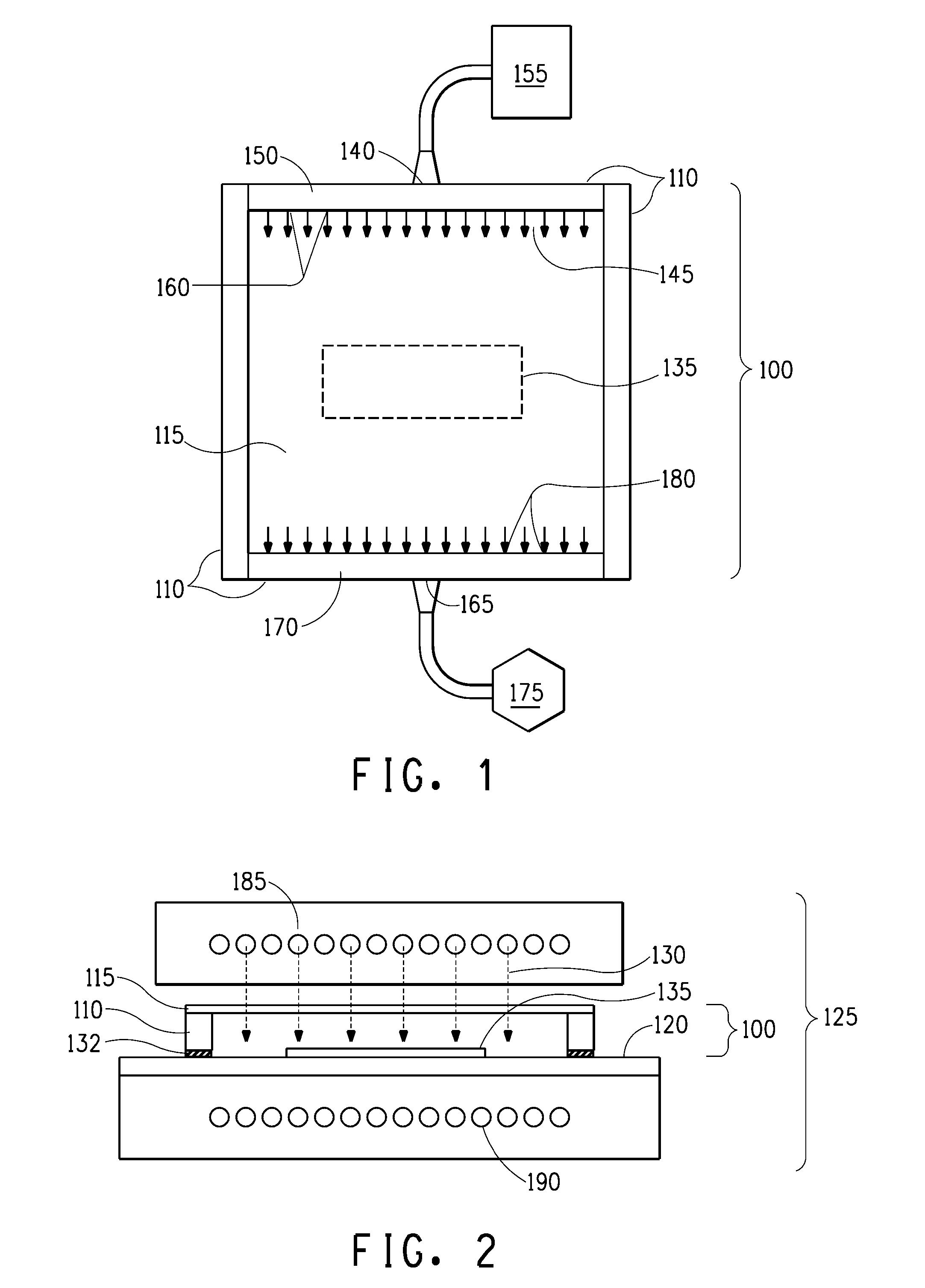
[0161]Modified digital workflow process described for Plate C in Example 1 was used for Example 2 with the following exceptions. Two oxygen meters were used; an Alpha Omega Series 2000, and Alpha Omega Series 3000, each measuring a different range of oxygen concentration. Several plates were prepared, i.e., exposed in the modified ECLF exposure unit, under different conditions, wherein exposure to actinic radiation was initiated when the oxygen concentration in the closed exposure chamber (as shown in FIGS. 1 and 2) reached 190,000 ppm; 150,000 ppm; 100,000 ppm; 20,000 ppm; and 10,000 ppm. The chamber continued to be purged of oxygen during exposure. Oxygen concentration was recorded every minute during the purging and exposure of the photosensitive element to actinic radiation.

[0162]Table 5 shows the oxygen concentration in the closed exposure chamber when the actinic radiation was initiated and the microscopic observation (Hirox 3D) of the wire frame images of the plates at the di...

example 3

[0165]Two photosensitive elements having a IR laser radiation sensitive layer (i.e., digital plates), CYREL® photopolymer printing elements type DPC-155, were imaged on an Esko Spark plate-setter with identical patterns to form an in-situ mask having regions of dots representing a range of dot areas including 2%, 10% and 30% of the area coverage. One plate was exposed to ultraviolet radiation using the standard, conventional digital workflow and processed as described above for Example 1, Plate B. The second plate was exposed to ultraviolet radiation using the modified (inert environment) workflow by placing the plate in a modified ECLF exposure unit. The modified ECLF exposure unit included a chamber consisting of a roof and four walls constructed of Lexan that resided on the bed of the exposure unit. The chamber was sealed from the external environment by applying tape along a perimeter of the chamber where the wall contacted the bed, and purged of atmospheric air by providing a c...


PUM

PropertyMeasurementUnit
diameteraaaaaaaaaa
diameteraaaaaaaaaa
transparentaaaaaaaaaa

Abstract

A relief printing form is prepared from a photosensitive element in an environment having controlled oxygen concentration during exposure to actinic radiation. An in situ mask is formed on a photosensitive element, the element is exposed to actinic radiation through the in-situ mask in an environment having an inert gas and a concentration of oxygen between 190,000 and 100 ppm, and the exposed element is treated to form the relief printing form having a pattern of raised surface areas.

Description

BACKGROUND OF THE INVENTION[0001]1. Field of the Disclosure[0002]This invention pertains to a method and an apparatus for preparing a relief printing form. More specifically, this invention describes a method and an apparatus for preparing the relief printing form from a photosensitive element that is exposed to actinic radiation in an environment having controlled oxygen concentration.[0003]2. Description of Related Art[0004]Flexographic printing plates are widely used for printing of packaging materials including corrugated carton boxes, cardboard boxes, continuous web of paper, and continuous web of plastic films. Flexographic printing plates are a form of relief printing in which ink is carried from a raised-image surface and transferred to a substrate. Flexographic printing plates can be prepared from photopolymerizable compositions, such as those described in U.S. Pat. Nos. 4,323,637 and 4,427,759. The photopolymerizable compositions generally comprise an elastomeric binder, a...

Claims


Application Information

Patent Timeline
Patent Type & Authority Patents(United States)
IPC IPC(8): G03F7/00G03C1/00
CPCG03F7/70858G03F7/2012G03F1/68G03F1/003G03F1/50
Inventor RUDOLPH, MICHAEL LEEPERROTTO, JOSEPH ANTHONYPATEL, DHIREN V.MCMILLEN, ROBERT A.
Owner DUPONT ELECTRONICS INC
Why Eureka
Try Eureka