Tube coupling device having check valve

a technology of coupling device and pipe, which is applied in the direction of screw threaded joints, service pipe systems, functional valve types, etc., can solve the problems of not being able to selectively couple two tubular members together, not being able to selectively control the water flowing between two tubular members that are coupled together, and being unable to selectively couple two tubular members

Inactive Publication Date: 2012-08-21
KUO KUANG MING
View PDF10 Cites 10 Cited by
  • Summary
  • Abstract
  • Description
  • Claims
  • Application Information

AI Technical Summary

Benefits of technology

[0015]The receptacle includes at least one protrusion extended therefrom, and the cover includes at least one depression formed therein for engaging with the protrusion of the receptacle and for anchoring the cover to the receptacle and for preventing the cover from being moved or rotated relative to the receptacle.
[0016]The receptacle includes at least one notch formed therein, and the cover includes at least one projection for engaging with the notch of the receptacle and for anchoring the cover to the receptacle and for preventing the cover from being moved or rotated relative to the receptacle.

Problems solved by technology

However, the valve members may only be used to selectively block the neck or the mouth piece or to control the water flowing through the neck or the mouth piece, but may not be used to selectively couple two tubular members together.
However, the typical conduit coupling or plumbing coupling device or joint also may not be used to selectively couple two tubular members together, and also may not be used to selectively control the water flowing between two tubular members that are coupled together.

Method used


Image

  • Tube coupling device having check valve
  • Tube coupling device having check valve
  • Tube coupling device having check valve

Examples


Embodiment Construction

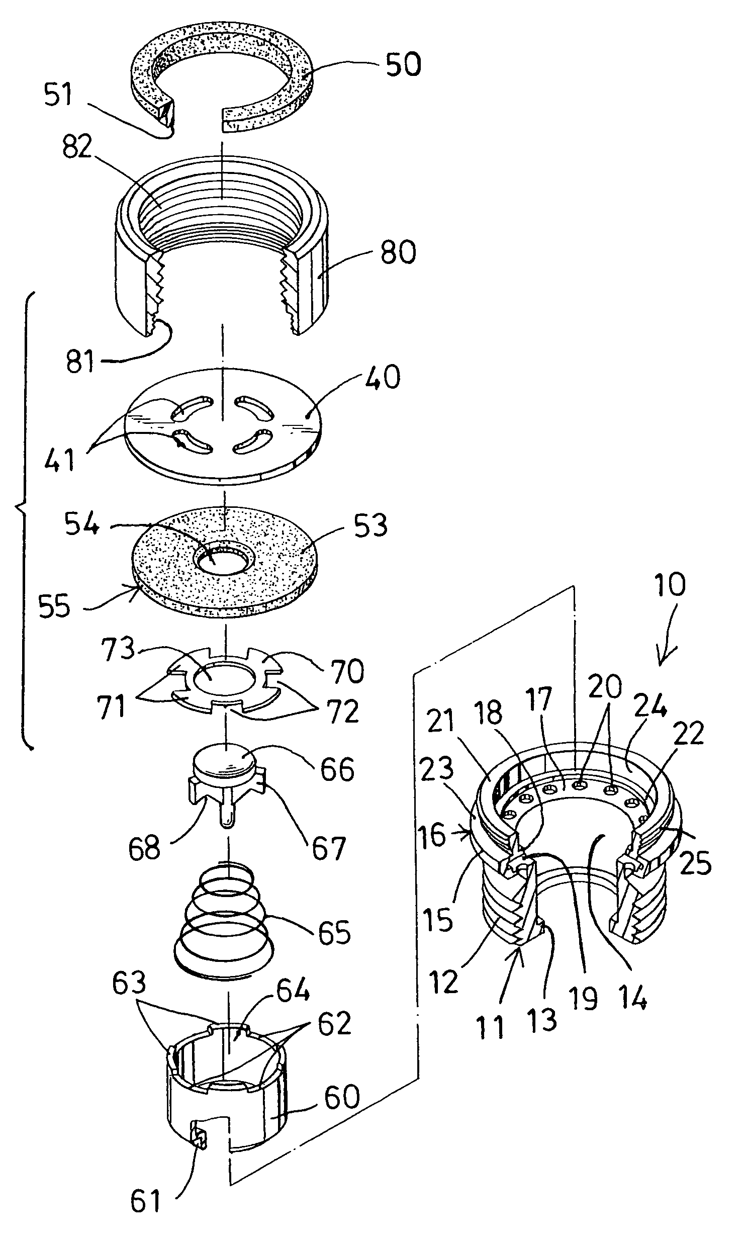
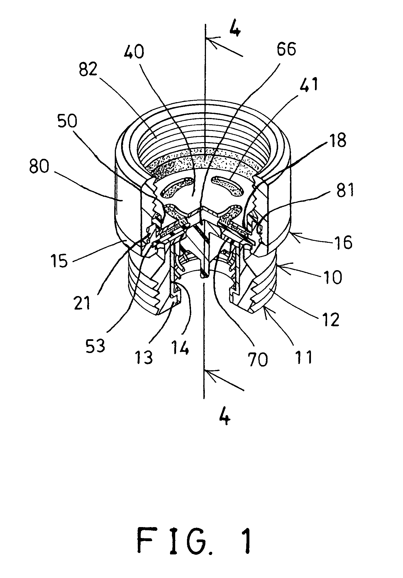
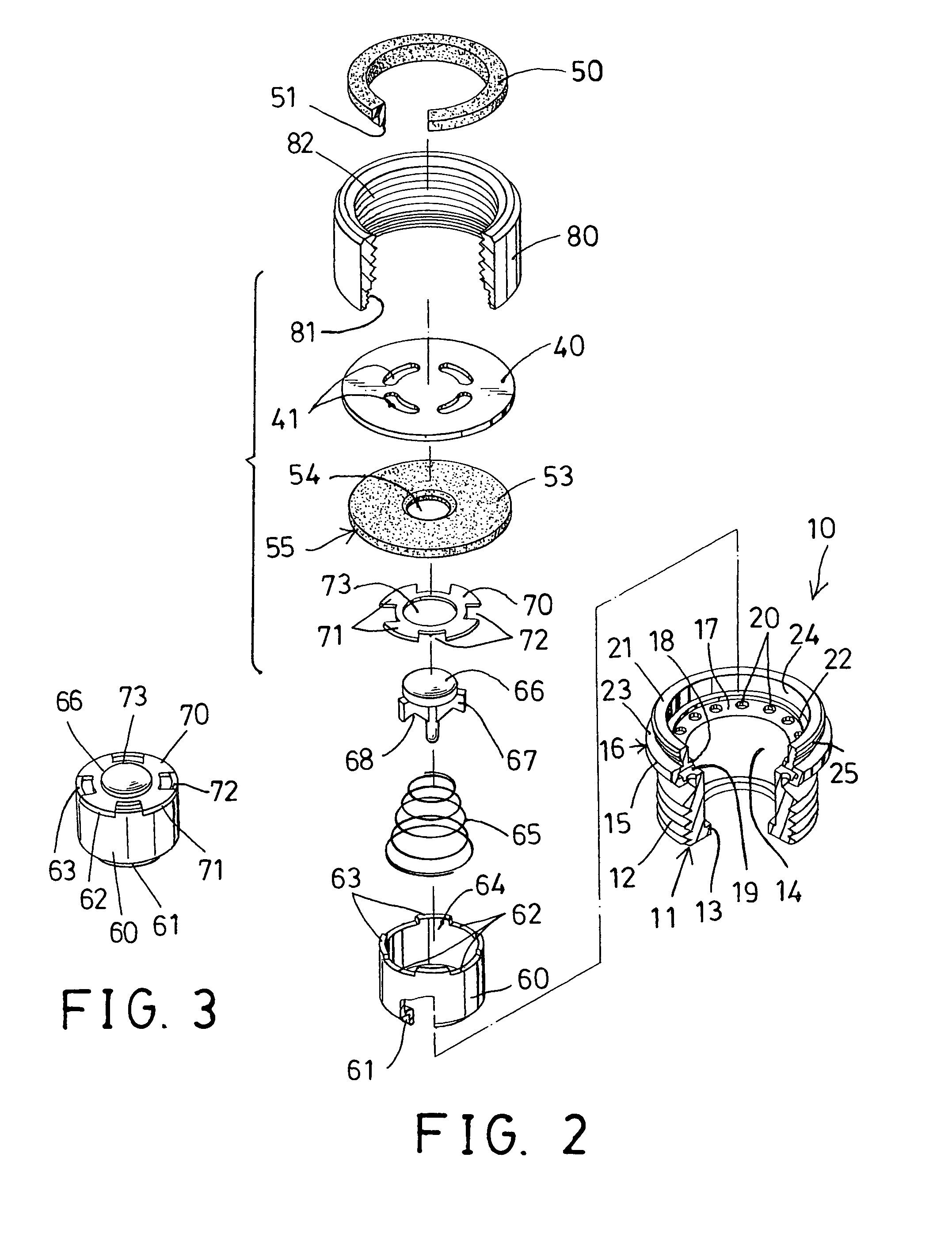
[0024]Referring to the drawings, and initially to FIGS. 1-4, a tube coupling device in accordance with the present invention comprises an intermediate and / or substantially cylindrical coupling body or member 10 including a lower portion 11 having an outer thread 12 formed thereon for threading or engaging with a tubular member 90 (FIGS. 4, 5) and for detachably attaching or mounting or securing or coupling the tubular member 90 to the coupling member 10, and including a peripheral rib 13 extended radially and inwardly therefrom, such as extended from the lower portion 11 of the coupling member 10, and including a chamber 14 formed in the lower portion 11 of the coupling member 10, and including a peripheral casing 15 formed or provided on or extended from the upper portion 16 of the coupling member 10, such as extended radially and outwardly from the upper portion 16 of the coupling member 10.

[0025]For example, the peripheral casing 15 includes a peripheral flange 17 extended latera...


PUM


Abstract

A tube coupling device includes a coupling member having an upper peripheral casing formed by a peripheral flange and a peripheral wall, a number of openings formed in the peripheral flange and communicative with an environment of the peripheral casing, a water guide plate engaged into the peripheral fence and engaged with the peripheral wall and having one or more passages, a partition member engaged into the peripheral casing and having a bore for water to flow into the coupling member, and a receptacle engaged into the coupling member, a valve member biased by a spring biasing member to engage with the partition member and to form a check valve.

Description

BACKGROUND OF THE INVENTION[0001]1. Field of the Invention[0002]The present invention relates to a tube or plumbing coupling device or joint, and more particularly to a tube coupling device including an improved washer or insulator mechanism for suitably coupling two tubular members together and for making a suitable water seal between the tubular members and having a check valve device for controlling the water flowing between the tubular members.[0003]2. Description of the Prior Art[0004]Typical valves or tube or conduit or plumbing coupling devices or joints comprise a pivotal valve member adapted to cooperate with a neck of a drain casing, and to constitute a closure for the neck of the drain casing.[0005]For example, U.S. Pat. No. 1,196,405 to Steeg, U.S. Pat. No. 1,204,316 to Renner, and U.S. Pat. No. 1,722,891 to Boosey disclose three examples of the typical conduit couplings or stop valves or backwater floor drains each also comprising a pivotal valve member pivotally or rot...

Claims


Application Information

Patent Timeline
Patent Type & Authority Patents(United States)
IPC IPC(8): E03C1/10
CPCE03B7/10E03C1/021E03C1/025E03C1/104F16K15/026F16K17/0473F16K24/06F16L15/008F16L15/08F16L55/07Y10T137/3294
Inventor KUO, KUANG-MING
Owner KUO KUANG MING
Why Eureka
Try Eureka