Bubble control unit, liquid ejecting head, and liquid ejecting apparatus

a control unit and liquid ejector technology, applied in the direction of printing, inking apparatus, etc., can solve the problems of difficult to completely prevent the mixing of bubbles, the inability to completely prevent the bubbles from being mixed, so as to reduce the number of cleaning operations and suppress the consumption of liquid

Active Publication Date: 2012-08-21
SEIKO EPSON CORP
View PDF28 Cites 10 Cited by
  • Summary
  • Abstract
  • Description
  • Claims
  • Application Information

AI Technical Summary

Benefits of technology

[0010]An advantage of some aspects of the invention is that it provides a bubble control unit, a liquid ejecting head, and a liquid ejecting apparatus capable of suppressing the consumption of liquid by reducing the number of executions of the cleaning operation.

Problems solved by technology

However, bubbles may intrude into the ink channel during the filling up (initial filling up) of ink within the recording head or the replacement of the ink cartridge and the like.
For this reason, it is difficult to completely prevent the bubbles from being mixed in.
If the bubbles intruding into the ink channel gradually grow to become larger, and a portion of the bubbles grown to an excessive size moves toward the pressure chamber due to the flow of ink, it may cause drawbacks of pressure loss due to absorption of the pressure fluctuation in operation of discharge by the bubbles, or shortage in supply of ink due to clogging of the channel by the bubbles, and the like.
However, in the above-mentioned recording head, since the filter is disposed parallel to the nozzle surface on which the nozzle is formed, and recent recording heads have been downsized, it has been difficult to augment the space for gathering the bubbles within the ink introducing needle, or to enlarge an area of the filter.

Method used


Image

  • Bubble control unit, liquid ejecting head, and liquid ejecting apparatus
  • Bubble control unit, liquid ejecting head, and liquid ejecting apparatus
  • Bubble control unit, liquid ejecting head, and liquid ejecting apparatus

Examples


Embodiment Construction

[0035]Hereinafter, the best embodiment for implementing the invention will be described with reference to the accompanying drawings and the like. In addition, although the embodiments described below are diversely confined as preferred specific examples of the invention, the scope of the invention is not limited to these embodiments unless stated that the invention is particularly confined in the description below. Further, in the embodiment, an ink jet type recording head (hereinafter, referred to as a “recording head”) as an example of the liquid ejecting head will be described by way of example.

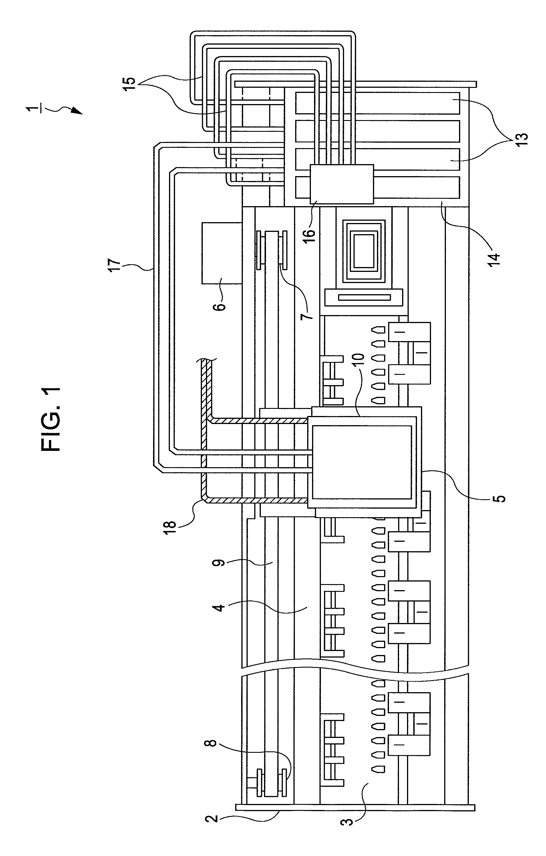
[0036]FIG. 1 is a plan view showing the configuration of an ink jet type recording apparatus on which a recording head 10 is mounted. First of all, the schematic configuration of the ink jet type recording apparatus on which the recording head is mounted (hereinafter, referred to as a printer) will be described with reference to FIG. 1. The illustrated printer 1 is an apparatus which disch...


PUM


Abstract

Provided is a bubble control unit for a liquid ejecting head which ejects liquid from a nozzle formed on a nozzle surface. The bubble control unit includes a liquid channel through which the liquid is supplied to the nozzle. In the bubble control unit, the liquid channel includes: a first chamber; a second chamber disposed on the upstream side from the first chamber; a first communicating path which has a bubble chamber extending upward from the first chamber, and makes the liquid within the second chamber to flow into the first chamber from a first communicating path inlet of the second chamber; and a second communicating path which is provided with a second communicating path inlet below the first communicating path inlet, separately from the first communicating path inlet, and makes the liquid within the second chamber to flow into the first chamber from the second communicating path inlet.

Description

[0001]This application claims priority to Japanese Patent Application No. 2008-218072, filed on Aug. 27, 2008, the entirety of which is hereby incorporated by reference.BACKGROUND[0002]1. Technical Field[0003]The present invention relates to a bubble control unit used in a liquid ejecting head for ejecting liquid from a nozzle such as an ink jet type recording head, a liquid ejecting head, and a liquid ejecting apparatus having the same.[0004]2. Related Art[0005]Liquid ejecting heads that discharge (eject) droplets from nozzle s by producing pressure fluctuations in liquid within a pressure chamber include, for example, an ink jet type recording head (hereinafter, simply referred to as a recording head) used in an image recording apparatus such as an ink jet type recording apparatus (hereinafter, simply referred to as a printer), a color material ejecting head used for manufacturing of a color filter such as a liquid crystal display, an organic EL (Electro Luminescence) display, an ...

Claims


Application Information

Patent Timeline
Patent Type & Authority Patents(United States)
IPC IPC(8): B41J2/19
CPCB41J2/14233B41J2/17509B41J2002/14419B41J2202/07
Inventor MIYAJIMA, HIROKI
Owner SEIKO EPSON CORP
Why Eureka
Try Eureka