Cleaning method, cleaning apparatus, and liquid ejecting apparatus

a technology of liquid ejecting apparatus and cleaning method, which is applied in the direction of cleaning equipment, transportation and packaging, pliable tubular containers, etc., can solve the problems of ink wastefulness in cleaning, broken meniscus of ink in the nozzle, etc., and achieve the effect of suppressing liquid consumption and preventing the breaking of meniscus

Active Publication Date: 2015-05-05
SEIKO EPSON CORP
View PDF5 Cites 0 Cited by
  • Summary
  • Abstract
  • Description
  • Claims
  • Application Information

AI Technical Summary

Benefits of technology

[0010]An advantage of some aspects of the invention is that it provides a cleaning method in which it is possible to suppress breaking of a meniscus in a nozzle while suppressing the consumption of liquid in cleaning, a cleaning apparatus, and a liquid ejecting apparatus.

Problems solved by technology

However, in naturally returning the negative pressure state of the closed space area to the atmospheric pressure state, since ink continues to be suctioned by the negative pressure of the closed space area for a relatively long time, there is concern that ink may be wastefully consumed in the cleaning.
Therefore, the air in the closed space area is drawn into a normal nozzle or a nozzle with air bubbles removed, so that there is concern that breaking of a meniscus of ink in the nozzle may occur.

Method used


Image

  • Cleaning method, cleaning apparatus, and liquid ejecting apparatus
  • Cleaning method, cleaning apparatus, and liquid ejecting apparatus
  • Cleaning method, cleaning apparatus, and liquid ejecting apparatus

Examples


first embodiment

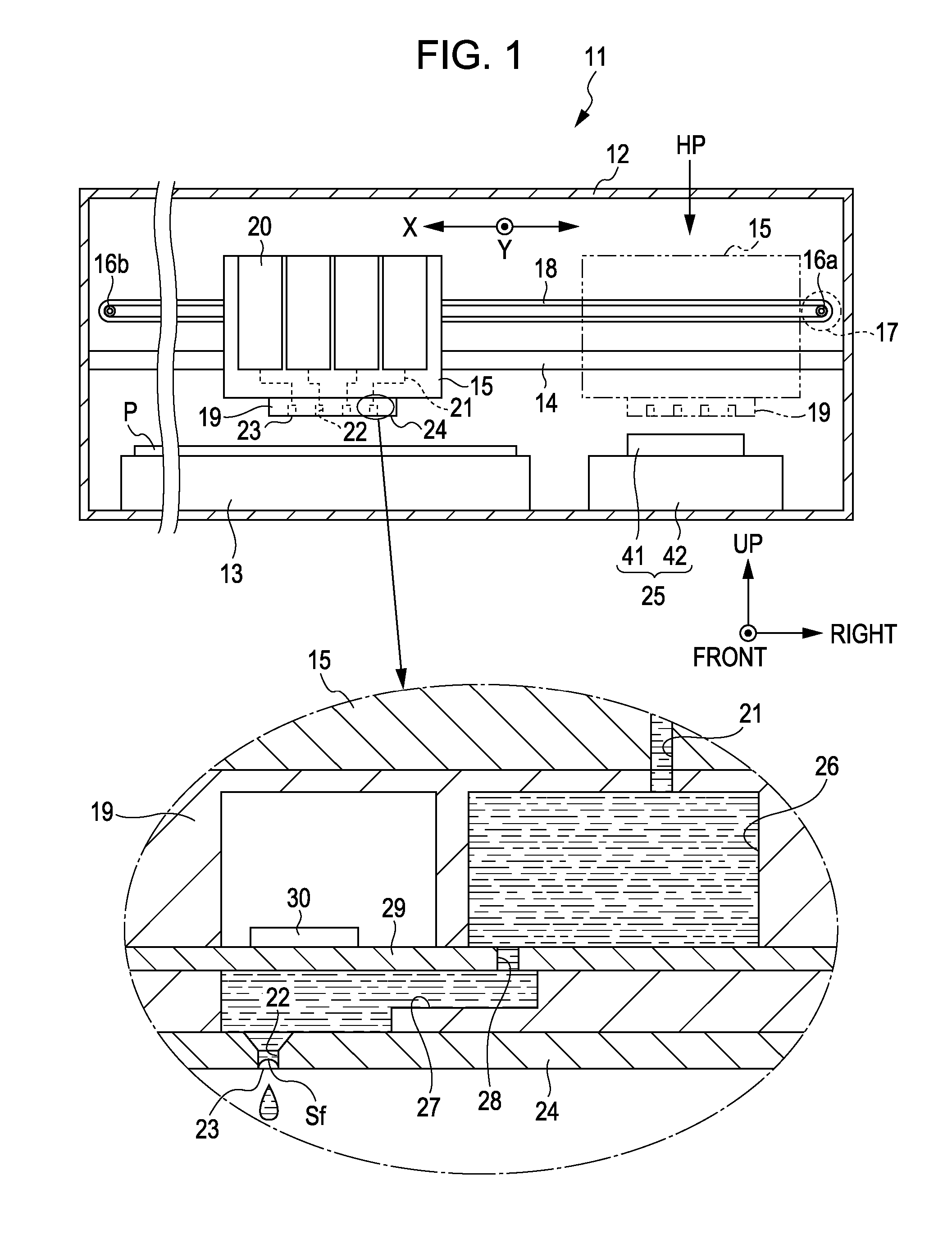
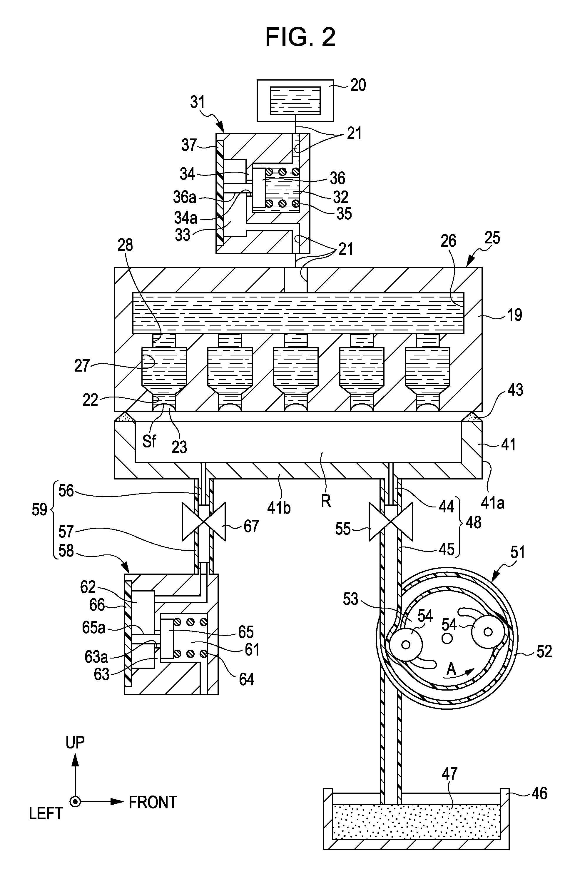
[0053]Hereinafter, a first embodiment in which the invention is embodied in an ink jet type printer (hereinafter also referred to as a “printer”) that is one type of a liquid ejecting apparatus will be described based on FIGS. 1 to 4. In addition, in the case of referring to a “front-and-back direction”, an “up-and-down direction”, and a “left-and-right direction” in the following explanation, unless expressly stated otherwise, they are set to refer to a “front-and-back direction”, an “up-and-down direction”, and a “left-and-right direction” which are indicated by arrows in each drawing. Also, a direction from the rear side toward the front side in the “front-and-back direction” in this case is equivalent to a transport direction (a sub-scanning direction) of a recording medium, the “up-and-down direction” is equivalent to a vertical direction, and the “left-and-right direction” is equivalent to a width direction (a main scanning direction) intersecting the transport direction of th...

second embodiment

[0097]Next, a second embodiment of the invention will be described based on FIGS. 5, 6A, and 6B. In addition, comparing the second embodiment with the first embodiment, the configuration of the cleaning apparatus 25 differs in some respects from that in the first embodiment and the other configurations are approximately the same as those in the first embodiment. Therefore, in the following, description is mainly made with respect to the different points from the first embodiment, and with respect to the same configuration, the same symbol is applied thereto and a repeated description is omitted.

[0098]As shown in FIG. 5, in the cleaning apparatus 25 of the second embodiment, the leading end side of the inflow tube 57 constituting a portion of the inflow flow path 59 is opened to the air. Further, in the inflow tube 57, between the leading end side of the inflow tube 57 and the second opening and closing valve 67, a pump 71 is disposed in place of the valve opened to the air 58. The p...

third embodiment

[0114]Next, a third embodiment of the invention will be described based on FIGS. 7, 8A, and 8B. In addition, comparing the third embodiment with the first and second embodiments, the configuration of the cleaning apparatus 25 differs in some respects from those in the first and second embodiments and the other configurations are approximately the same as those in the first and second embodiments. Therefore, in the following, description is mainly made with respect to the different points from the first and second embodiments, and with respect to the same configuration, the same symbol is applied thereto and a repeated description is omitted.

[0115]As shown in FIG. 7, in the cleaning apparatus 25 of the third embodiment, a pump 81 which is a single tube pump is disposed midway on the discharge flow path 48 and the inflow flow path 59.

[0116]That is, the pump 81 has an approximately cylindrical pump case 82 and also an intermediate portion in the longitudinal direction of the discharge ...


PUM


Abstract

In the printer, after ink is discharged from nozzle openings by making a closed space area, formed by bringing a cap into contact with a recording head, enter into a negative pressure state due to negative pressure accumulated in a discharge flow path by driving a pump, when making the negative pressure state of the closed space area be subjected to a pressure change in a direction of coming to an atmospheric pressure state, after the air flows into the closed space area by making a second opening and closing valve provided at an inflow flow path which makes the closed space area and an aerial space communicate with each other be in an opened state, the inflow of the air into the closed space area through the inflow flow path is stopped in a state where negative pressure remains in the closed space area.

Description

CROSS REFERENCES TO RELATED APPLICATIONS[0001]The entire disclosure of Japanese Patent Application Nos. 2010-265182, filed Nov. 29, 2010, 2010-265183, filed Nov. 29, 2010, and 2010-269478, filed Dec. 2, 2010 are expressly incorporated herein by reference.BACKGROUND[0002]1. Technical Field[0003]The present invention relates to a cleaning method, a cleaning apparatus, and a liquid ejecting apparatus.[0004]2. Related Art[0005]Heretofore, as one type of a liquid ejecting apparatus which ejects liquid onto a recording medium, an ink jet type printer has been widely known. The printer performs recording on the recording medium by ejecting ink (liquid) from nozzle openings formed in a liquid ejecting head.[0006]The printer performs so-called cleaning in which in a state where a closed space area is formed by bringing a bottomed box-shaped cap into contact with the liquid ejecting head so as to surround the nozzle openings which eject ink, suction is performed on the closed space area by a ...

Claims


Application Information

Patent Timeline
Patent Type & Authority Patents(United States)
IPC IPC(8): B08B5/04B08B7/04B41J2/165B41J2/175
CPCB41J2/16532B41J2/16526B41J2/17596
Inventor MATSUMOTO, DAISUKEYAMADA, YOICHIKOBASHI, MASARU
Owner SEIKO EPSON CORP
Why Eureka
Try Eureka