
Liquid ejection apparatus and control method for applying meniscus vibration according to the viscosity states of nozzles

a liquid ejection and nozzle technology, applied in the direction of printing, other printing apparatus, etc., can solve the problems of not being able to perform ejection for its original purpose, not being able to perform printing, and being unable to achieve the effect of printing, etc., to reduce the frequency of purging and suctioning, reduce the volume of evaporation, and suppress the consumption of liquid

Inactive Publication Date: 2010-04-27
FUJIFILM CORP
View PDF8 Cites 1 Cited by
  • Summary
  • Abstract
  • Description
  • Claims
  • Application Information

AI Technical Summary

Benefits of technology

This approach reduces the frequency of purging and suctioning, minimizes ink consumption, and enhances printing productivity by maintaining ink viscosity over a longer period, thus extending the life of the actuator and reducing energy usage.

Problems solved by technology

Therefore, eventually, beneficial effects cease to be obtained, even if the vibrating action is performed.
During purging or during a maintenance operation, it is not possible to perform ejection for its original purpose.
In other words, a waiting time arises during which it is not possible to perform printing.
Furthermore, suctioning generally requires longer time than purging.

Method used


Image

  • Liquid ejection apparatus and control method for applying meniscus vibration according to the viscosity states of nozzles
  • Liquid ejection apparatus and control method for applying meniscus vibration according to the viscosity states of nozzles
  • Liquid ejection apparatus and control method for applying meniscus vibration according to the viscosity states of nozzles

Examples


Embodiment Construction

General Composition of Image Forming Apparatus

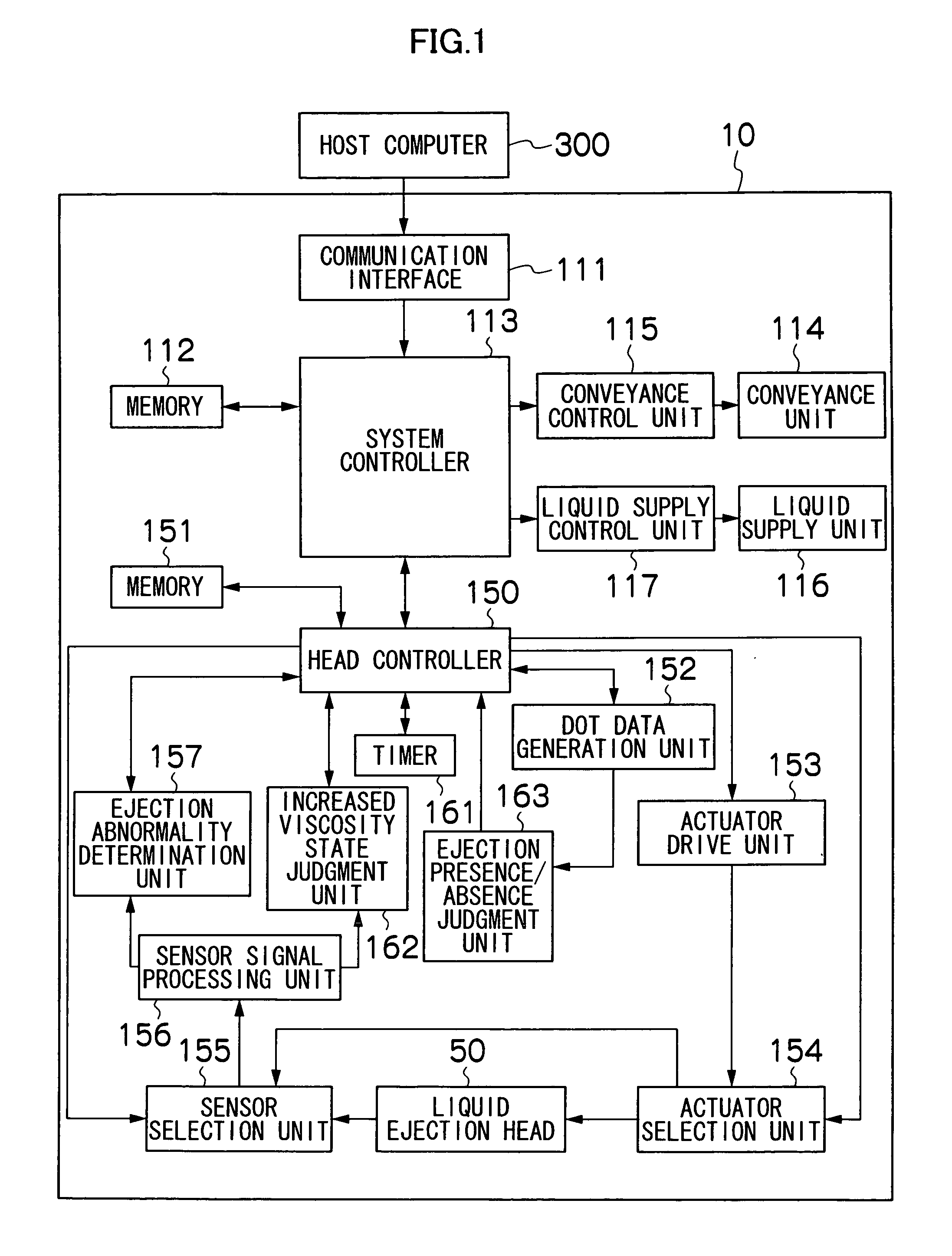
[0043]FIG. 1 is a block diagram showing the general composition of an image forming apparatus corresponding to a liquid ejection apparatus according to an embodiment of the present invention.

[0044]The image forming apparatus 10 shown in FIG. 1 comprises: a communication interface 111; memories 112 and 151; a system controller 113; a conveyance unit 114; a conveyance control unit 115; a liquid supply unit 116; a liquid supply control unit 117; a head controller 150; a dot data generation unit 152; an actuator drive unit 153; an actuator selection unit 154; a sensor selection unit 155; a sensor signal processing unit 156; an ejection abnormality determination unit 157; a timer 161; an increased viscosity state judgment unit 162; and an ejection presence / absence judgment unit 163.

[0045]The communication interface 111 is an image data input device for receiving image data transmitted by a host computer 300. For the communication interface 11...


PUM


Abstract

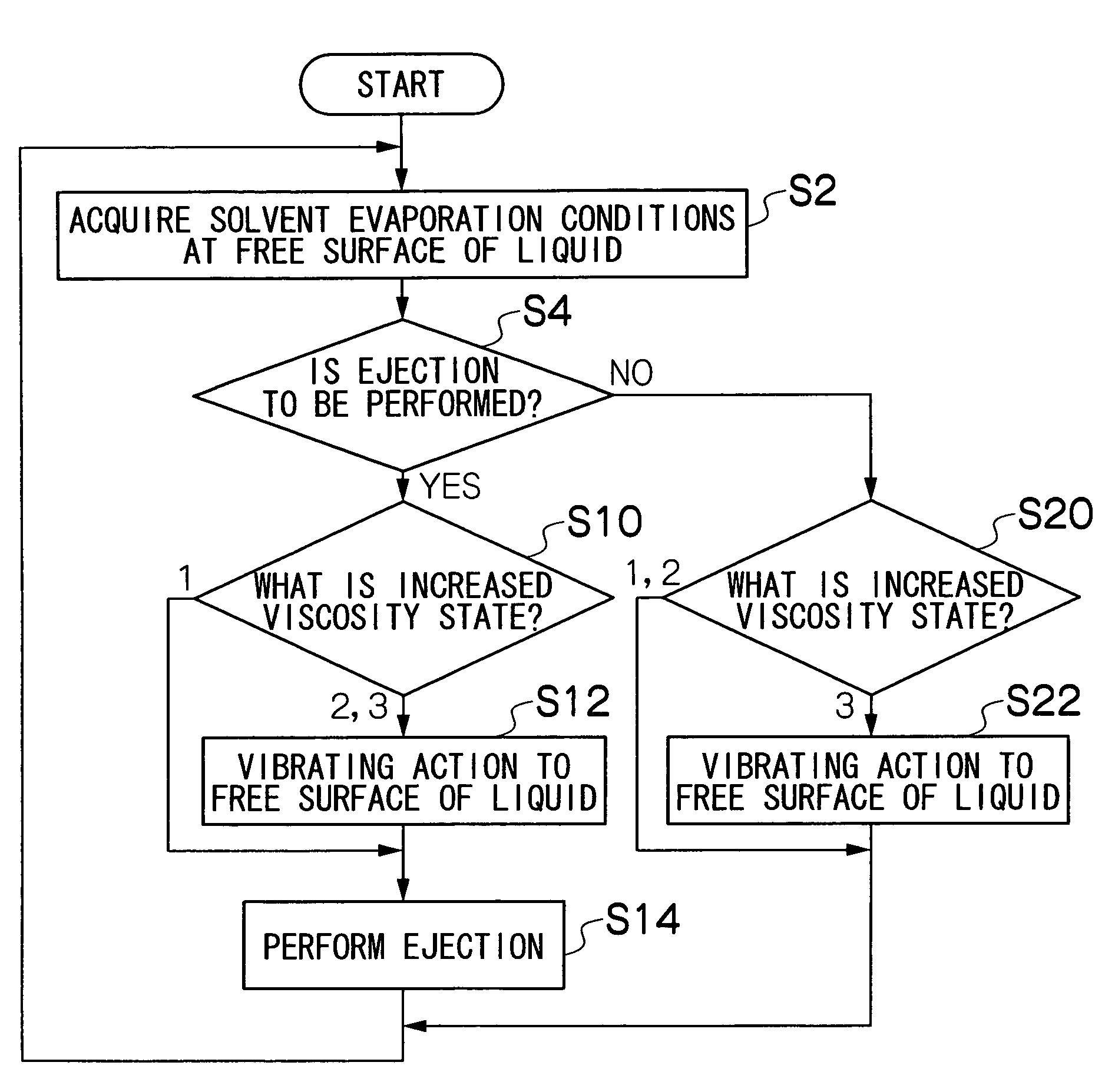
A liquid ejecting apparatus with a pressure chamber connected to an ejection nozzle that applies pressure to liquid that causes the liquid to be ejected from the nozzle. An actuator is provided to vibrate a free surface of the liquid in the nozzle without ejecting the liquid from the nozzle. A viscosity state judgment device judges the existence of a first viscosity state near the free surface of the liquid indicating that liquid ejection from the nozzle is possible without applying vibrations, a second state indicating that liquid ejection from the nozzle is possible if vibrations are applied, and a third state indicating that liquid ejection from the nozzle is not possible but restoration to the first state is possible if the vibrating action is performed. A control device then controls liquid ejection from the nozzle based on the judged state.

Description

BACKGROUND OF THE INVENTION[0001]1. Field of the Invention[0002]The present invention relates to a liquid ejection apparatus and a control method for a liquid ejection apparatus, and more particularly, to a liquid ejection apparatus and a control method for a liquid ejection apparatus in which vibrating action is performed to free surfaces of liquid in nozzles.[0003]2. Description of the Related Art[0004]A liquid ejection apparatus is known which performs vibrating action to liquid in order to prevent the viscosity of the liquid from increasing nearby a free surface (the liquid-atmosphere interface, which is also commonly called “meniscus”) of the liquid inside a nozzle (a liquid ejection port).[0005]More specifically, as shown in FIG. 12A, the solvent of ink evaporates from the free surface of the ink in a nozzle 51 due to the difference in the vapor pressure of the solvent between the atmosphere and the ink in the nozzle 51, and as shown in FIG. 12B, the ink inside the nozzle 51 i...

Claims


Application Information

Patent Timeline
Patent Type & Authority Patents(United States)
IPC IPC(8): B41J2/165B41J29/38B41J2/45
CPCB41J2/165B41J2/1721B41J2/17563B41J2/17509B41J2002/16502B41J2002/14354B41J2/16502
Inventor NAGASHIMA, KANJI
Owner FUJIFILM CORP
Learn More