Method of coproducing methanol and ammonia

a technology of methanol and ammonia, which is applied in the direction of chemical/physical processes, bulk chemical production, energy input, etc., can solve the problems of inability to carry out the production of only one of the two, the production amount of either one is remarkably small, so as to achieve the effect of efficient co-production of methanol and without increasing the specific raw material consumption

Active Publication Date: 2012-08-21
TOYO ENG CORP
View PDF11 Cites 10 Cited by
  • Summary
  • Abstract
  • Description
  • Claims
  • Application Information

AI Technical Summary

Benefits of technology

[0018]The present invention has been made in view of the problems of the conventional technologies described above, and it is an object to provide a method of coproducing methanol and ammonia, which can efficiently coproduce methanol and ammonia in terms of reactivity and economy, and can optionally select the single production of either one without being largely reduced in amount from the designed capacity of the equipment, and also can change the production ratio of methanol and ammonia almost without increasing or decreasing the specific raw material consumption.
[0019]A large amount of excess hydrogen is generated and used as fuel in a conventional methanol production process using natural gas as a raw material, while a large amount of carbon dioxide is by-produced in a conventional ammonia production process using natural gas as a raw material and carbon dioxide is released in the atmosphere when there is no adjacent urea plant. Therefore, the present inventors have come up with the idea that it becomes possible to increase the production of both methanol and ammonia considerably, even without increasing the design capacity of the desulfurization and the steam reforming in the methanol production unit and the desulfurization and the primary and secondary reformings in the ammonia production unit (that is, without increasing specific consumption of natural gas) by producing a synthesis gas for methanol, by way of directing the carbon dioxide by-produced in the ammonia production unit to the methanol production unit to be reacted with the excess hydrogen of the methanol production unit according to the formula (2) described above, and also by preparing a feedstock gas for ammonia synthesis, by way of further approximately purifying and separating the hydrogen remaining in the purge gas and combining it with the feedstock synthesis gas of the ammonia production unit, and thus they have reached the present invention enabling the coproduction of methanol and ammonia that uses a remarkably smaller amount of natural gas as compared with the case of independently producing each of methanol and ammonia.
[0026]According to the present invention, it has advantages of being capable of making effective use of the purge gas from methanol synthesis and the off gas from ammonia synthesis, being capable of efficiently coproducing methanol and ammonia, and being further capable of optionally selecting the coproduction ratio of methanol and ammonia almost without increasing the specific raw material consumption even when singly producing either one of them or even when coproducing them by adjusting the amount of carbon dioxide supplied from the CO2 removing step (B-4) to the methanol synthesis process.

Problems solved by technology

However, the conventional coproduction technologies described above have the following problems.
Those production methods are such that, as described above, the production amount of either one is remarkably small and can hardly be referred to as coproduction or can be referred to as by-production or that it is almost impossible to carry out the production of only either one.
In addition, because nitrogen is an inert gas for methanol synthesis, a synthesis gas for ammonia, for which the amount of nitrogen required is determined by the amount of air as an oxygen source for the secondary reformer, has an excessively large amount of unreacted hydrogen and carbon monoxide entrained by the purge gas from the methanol synthesis section, and causes both a low hydrogen conversion efficiency and a low carbon conversion efficiency.
Hence, the conventional technologies described above cannot be admitted at all as being superior in efficiency, in terms of the specific raw material consumption, as compared with single production of each of methanol and ammonia.

Method used


Image

  • Method of coproducing methanol and ammonia
  • Method of coproducing methanol and ammonia
  • Method of coproducing methanol and ammonia

Examples


example 1

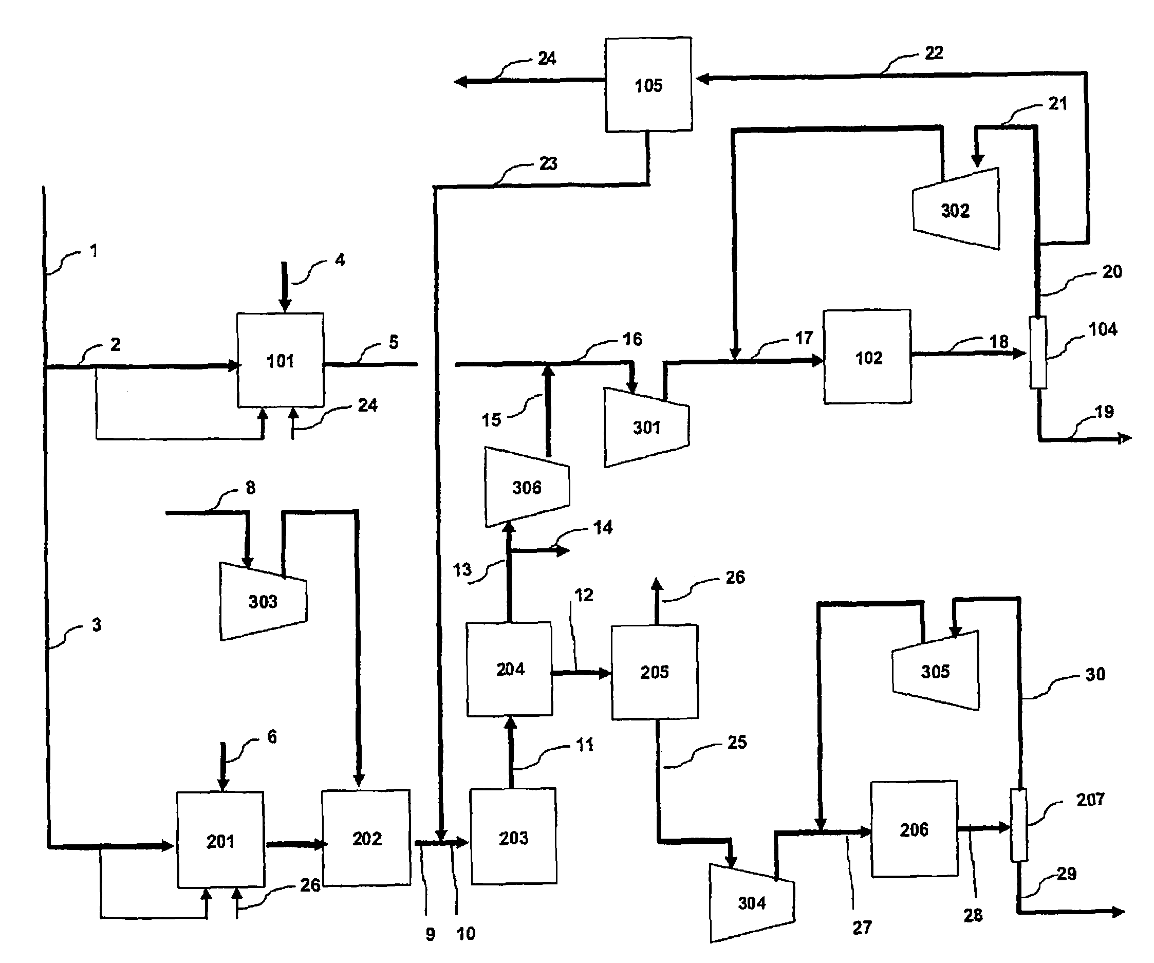
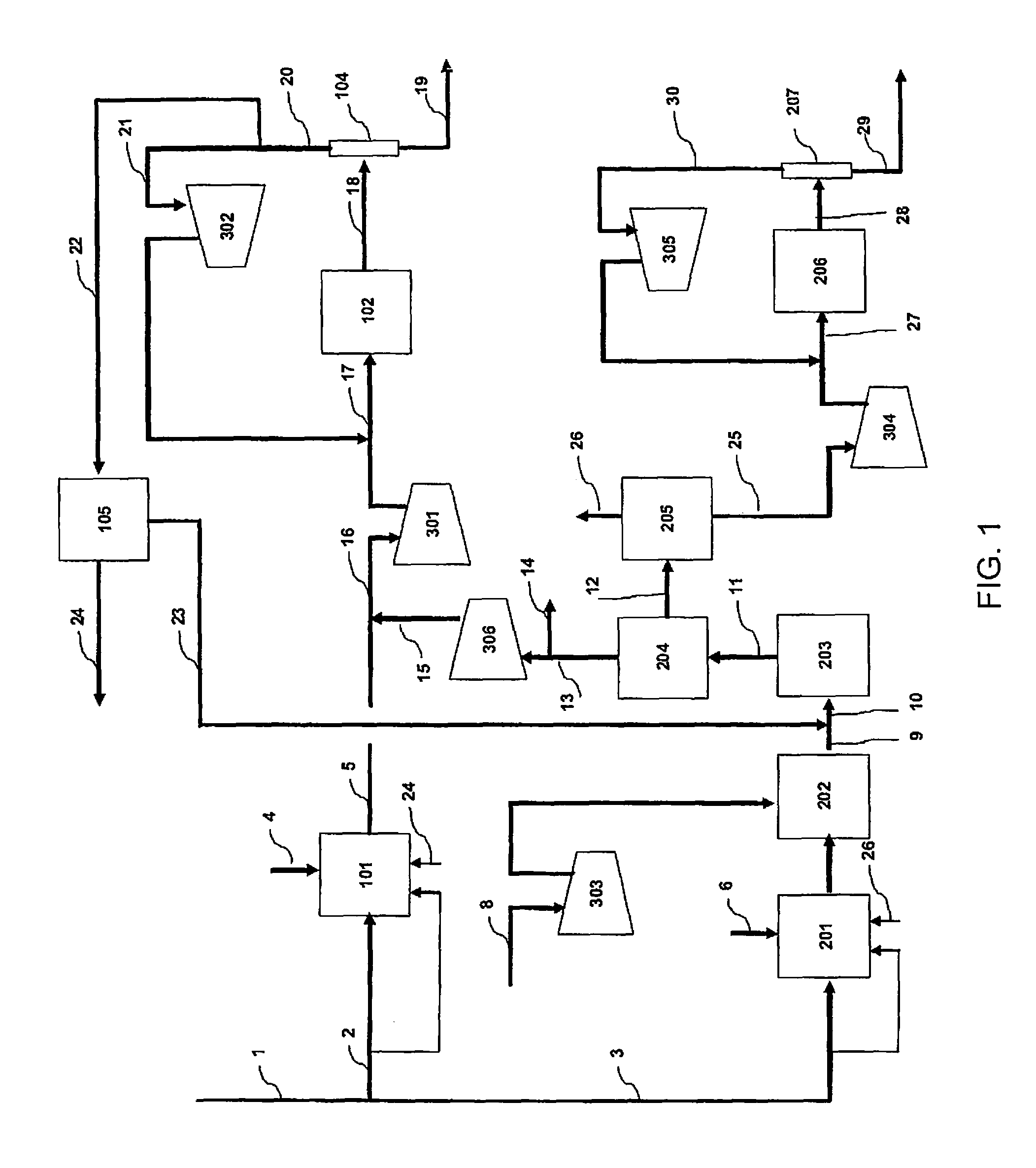
[0056]In the flow scheme of FIG. 1, natural gas having the composition of Table 1 is supplied through the flow path 1 to a process for coproducing methanol and ammonia.

[0057]

TABLE 1Composition of Raw Material Natural Gas (Lower HeatingValue: 861.57 MJ / kmol)mol %Methane82.64Ethane7.56Propane2.12Isobutane0.59n-butane0.57n-pentane0.49Carbon Dioxide5.38Nitrogen0.65Total100.00

[0058]Table 2, Table 3 and Table 4 show the mass balance of the Example. The left column indicates the number of each line shown in FIG. 1, and the top rows indicate the pressure, the temperature, the flow rate, and / or the composition flowing in each line.

[0059]

TABLE 2PressureTemperatureFlow RateNumberMpa° C.kmol / hrNotes12.5825821922.58254050as raw material1453as fuel32.58252522as raw material194as fuel

[0060]

TABLE 3PressureTemperatureComposition (mol %)Flow RateNumberMPa° C.CH4COCO2H2O2N2 + ArCH3OHNH3H2OKmol / hr42.9527310012,99552.008752.110.75.749.00.132.425,74164.623551007,57274.0771315.22.56.726.30.30.049.112,0958...

example 2

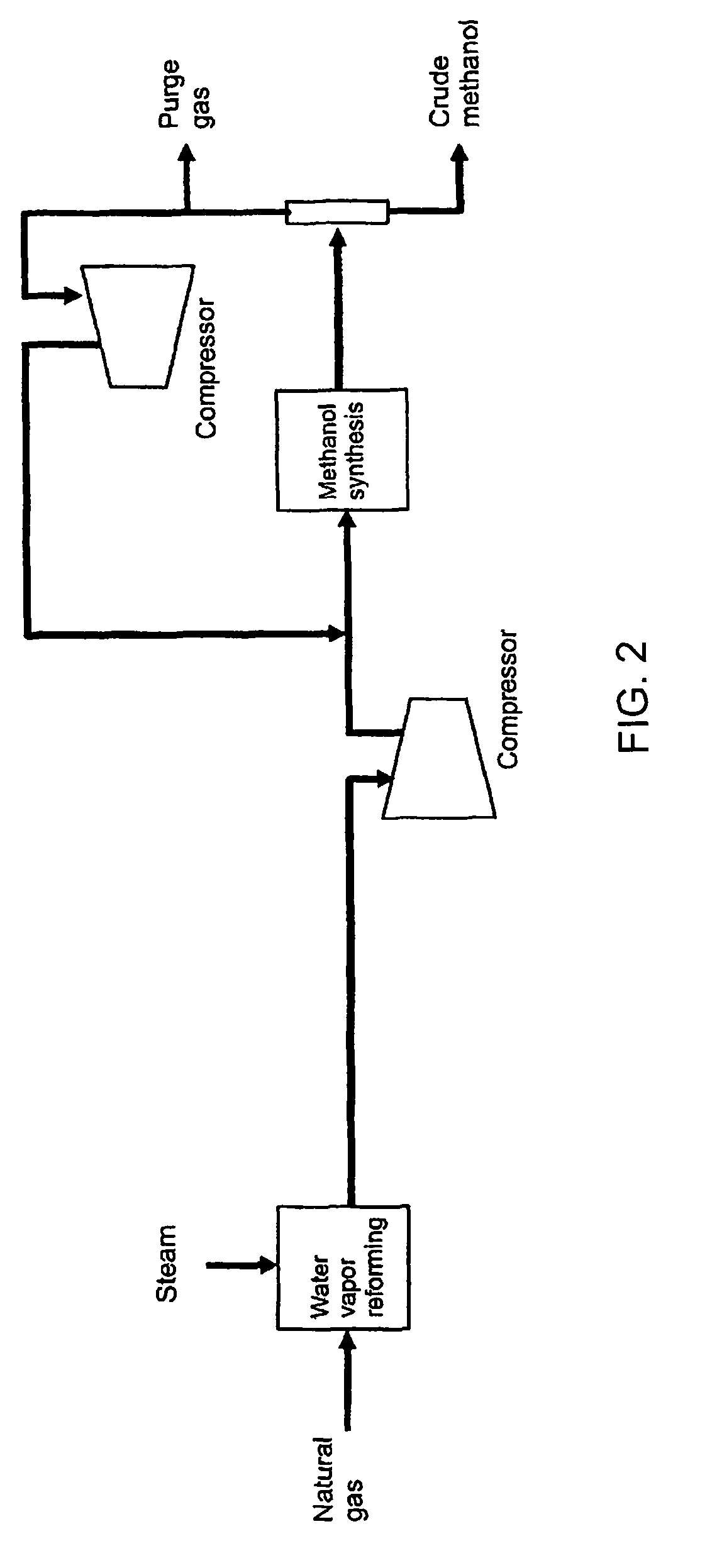
[0066]In a methanol process shown by the flow scheme of FIG. 2 using 4050 kmol / hr of natural gas as raw material and an ammonia process shown by the flow scheme of FIG. 3 using 2522 kmol / hr of natural gas as a raw material, each natural gas being the amount equal to that of Example 1 described above, when the mass balance is calculated in the case of not using the carbon dioxide, which is removed in the ammonia process, for the methanol process, the amount of methanol production is naturally 3000 t / day, and as a conclusion of a standard balance calculation by those skilled in the art, it is determined that the amount of ammonia production is 2765 t / day, and the amounts of methanol and ammonia are the same as those of the Example 1 on a weight basis. In addition, it is also calculated that the specific consumptions of natural gas are also the same as that of the Example 1. Likewise, it becomes clear that the present invention provides a remarkable energy saving effect as compared wit...

reference example 1

[0069]In the methanol synthesis step 102 in FIG. 1 in Example 1 described above, given that methanol is produced in the same amount using a catalyst in the same amount as the amount of the catalyst required in the case of employing a reactor, as the reactor to which the mass balance shown in Table 3 is given, removing the heat of reaction in the form of steam generation by indirectly cooling a large number of reaction tubes that supply the boiler water to the shell side and are packed with the catalyst, when using a reactor having the characteristics of being capable of designing the temperature of operation at each point of the catalyst layers where the methanol synthesis reaction occurs so as to respectively have the maximum value of the reaction rate of methanol synthesis, at least the mass balance of the synthesis loops shown in Table 7 and Table 8 is obtained as easily estimated by those skilled in the art because of the structure provided with boiler tubes for generating steam...


PUM

PropertyMeasurementUnit
pressureaaaaaaaaaa
temperatureaaaaaaaaaa

Abstract

The present invention provides a process of coproducing methanol and ammonia by using natural gas, LPG, butane, or naphtha as a raw material, having a methanol production process (A) composed of specific steps and an ammonia production process (B) also composed of specific steps.

Description

TECHNICAL FIELD[0001]The present invention relates to a technology for coproducing methanol and ammonia from synthesis gas obtained from reforming a hydrocarbon, such as natural gas, liquid petroleum gas, butane, naphtha and so on.BACKGROUND ARTS[0002]Both technologies for the production of methanol and for the production of ammonia use hydrogen as a main raw material and require technology to produce a synthesis gas containing hydrogen and carbon monoxide, and the production process of ammonia comprises sections derived from the technologies to produce a synthesis gas by reforming raw materials similar to those to produce a synthesis gas for methanol synthesis, and further includes a section to generate carbon dioxide and hydrogen by CO conversion of the synthesis gas formed by steam reforming, a section to remove carbon dioxide which is increased by an equal amount through the CO conversion, and a section to purify hydrogen to be suitable as a feedstock for ammonia synthesis by re...

Claims


Application Information

Patent Timeline
Patent Type & Authority Patents(United States)
IPC IPC(8): C07C27/14C01C1/04
CPCB01J8/0411B01J8/0496C01B3/025C01B3/38C01B3/382C01C1/0488C07C29/1518C07C31/04B01D53/047B01D2256/16B01J2208/00353B01J2219/00006C01B2203/0233C01B2203/0244C01B2203/025C01B2203/0283C01B2203/0405C01B2203/0415C01B2203/043C01B2203/0445C01B2203/0475C01B2203/061C01B2203/068C01B2203/1235C01B2203/141C01B2203/148Y02C10/08Y02C10/10Y02P20/129Y02P20/52Y02C20/40Y02P20/50Y02P20/151
Inventor YOSHIDA, NOBUHIROHIROTANI, KUNIO
Owner TOYO ENG CORP
Why Eureka
Try Eureka