
Rear element for a motor vehicle comprising a lighting unit

a technology for rear elements and motor vehicles, which is applied in vehicle interior lighting, transportation and packaging, and light and heating equipment, etc., can solve the problem that the illumination element should not be able to be easily dismantled from the rear-end element, and achieve the effect of excellent property profile and wide scop

Inactive Publication Date: 2012-08-28
EVONIK ROEHM GMBH
View PDF17 Cites 0 Cited by
  • Summary
  • Abstract
  • Description
  • Claims
  • Application Information

AI Technical Summary

Benefits of technology

[0010]In the light of the prior art, it was now an object of the present invention to provide a rear-end element for a motor vehicle which has an excellent property profile. In particular, the illumination element should not be capable of easy dismantling from the rear-end element. The illumination element should moreover have minimum effect on the design of the rear-end element, in order to give the designers wide scope for design of the motor vehicle.
[0011]Another object of the invention consisted in providing a rear-end element for a motor vehicle with an illumination unit, where the rear-end element can be produced quickly and with particular ease. It should be possible here to obtain the rear-end element at particularly low cost.
[0012]Another object of the present invention was to provide a rear-end element of the type described above whose illuminant can be selected freely.

Problems solved by technology

In particular, the illumination element should not be capable of easy dismantling from the rear-end element.

Method used


Image

  • Rear element for a motor vehicle comprising a lighting unit
  • Rear element for a motor vehicle comprising a lighting unit
  • Rear element for a motor vehicle comprising a lighting unit

Examples


Embodiment Construction

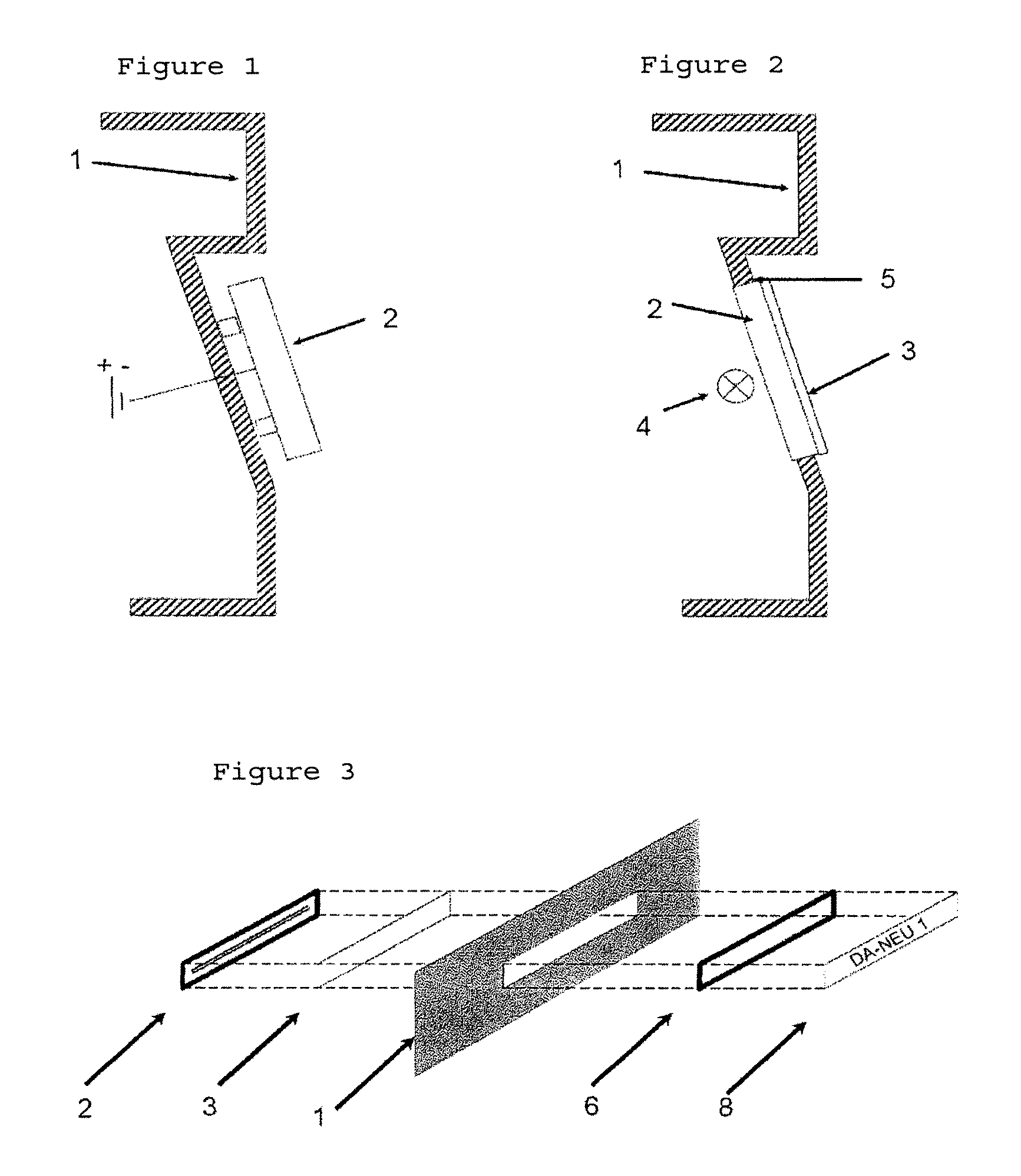
[0061]FIG. 1 is a diagrammatic cross section of a rear-end element (1) which here is a rear flap of the prior art. The illumination unit (2) of the number plate here is applied to the rear flap, and this is therefore not an integral unit of the rear flap, but has to be considered to be an add-on part.

[0062]In contrast to this, FIG. 2 describes a rear-end element (1) which here is a rear flap according to the present invention. The illumination unit (2), which encompasses a translucent body (3) and also an illuminant (4), forms an integral constituent of the rear-end element (1). The translucent body (3) here is introduced by way of the side areas (5) into the rear flap.

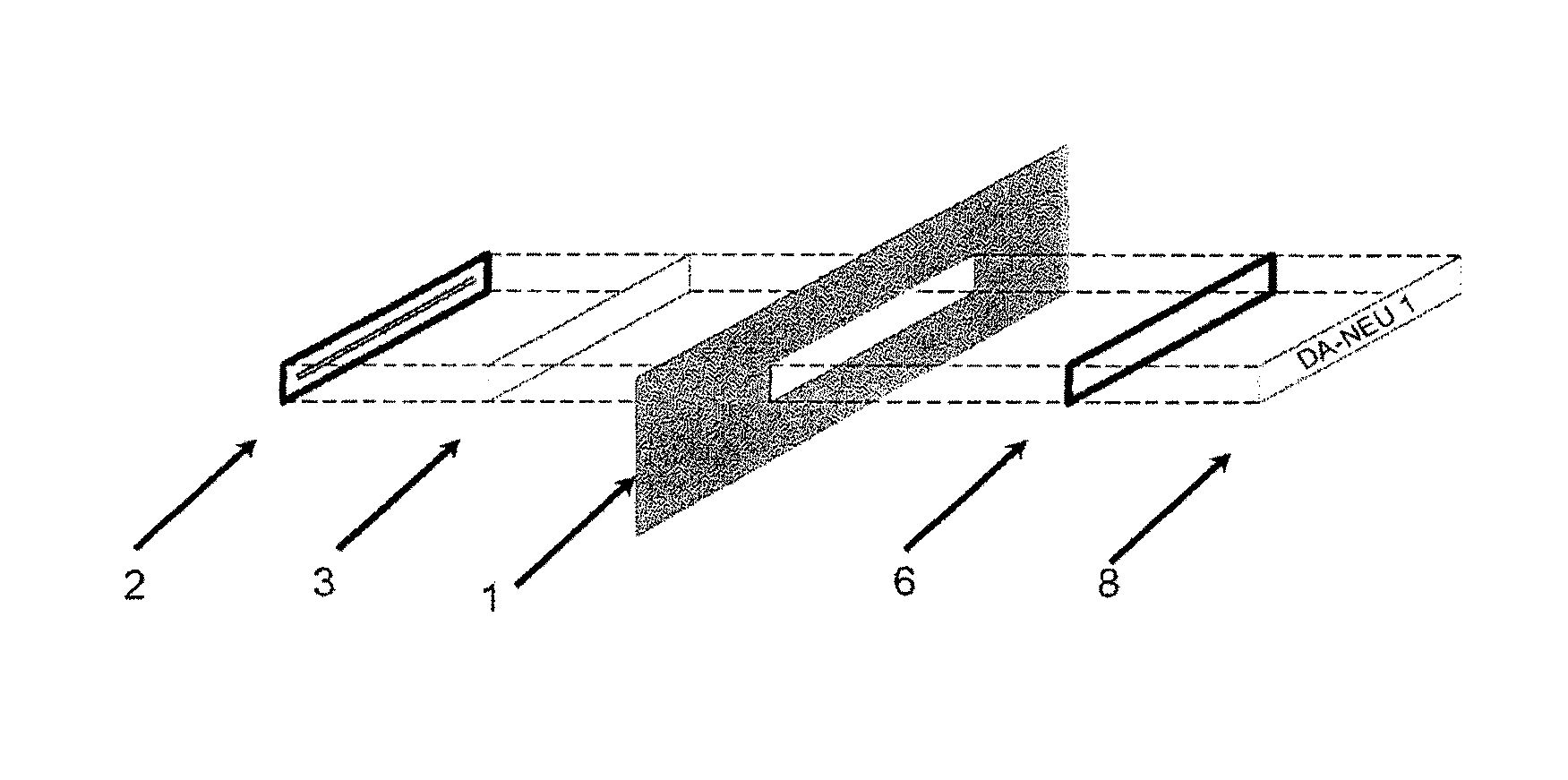
[0063]To illustrate this structure, FIG. 3 shows an exploded perspective view of a rear-end element (1), which here is a rear flap, with an illumination unit (2). The present embodiment of the rear flap (1) encompasses a component into which the translucent body (3) is introduced. This component can be interpreted as ...


PUM


Abstract

The present invention relates to a rear-end element (1) for a motor vehicle encompassing an illumination unit (2) for the illumination of a number plate, where the illumination unit (2) illuminates the rear side of the number plate and the illumination unit (2) has a translucent body (3) and an illuminant (4), where the translucent body of the illumination unit (2) has been introduced by way of the side area (5) into the rear-end element (1). The present invention moreover describes a motor vehicle which encompasses a rear-end element described above.

Description

BACKGROUND OF THE INVENTION[0001]The present invention relates to a rear-end element for a motor vehicle encompassing an illumination unit for the illumination of a number plate, where the illumination unit illuminates the rear side of the number plate.[0002]Number plates of motor vehicles are generally illuminated via two or three lamps which have been attached above or below the number plate. However, a disadvantage is that the number plate is not uniformly illuminated. The illuminants attached externally above and below the plate moreover restrict the opportunities for optimizing the design of the vehicle.[0003]There are also known illumination devices which illuminate the number plate via a light source attached at the rear. By way of example, illuminant foils or optically conductive bodies can be used as light source. Embodiments of this type for the illumination of number plates have been described by way of example in the publications WO 2007 / 012306, EP-A-1 262 373 and EP-A-1...

Claims


Application Information

Patent Timeline
Patent Type & Authority Patents(United States)
IPC IPC(8): B60Q1/56
CPCB60Q1/56B60R13/10
Inventor SCHROEBEL, SVENBLASS, RUDOLFHALBLAENDER, ANTON
Owner EVONIK ROEHM GMBH
Learn More