Method and system for manufacturing foamed polyolefin tapes at cost effective line speeds

a polyolefin tape and line speed technology, applied in the field of foamed, oriented tape yarn production, can solve the problems of reducing the strength of the starting tape, not providing information on a sequence of specific steps and/or processes, and much of the conventional art does not articulate how these foamed tapes can be manufactured. , to achieve the effect of high surface to volume ratio, good property profile and high haul off speed

Active Publication Date: 2012-08-21
PROPEX FURNISHING SOLUTIONS INC
View PDF10 Cites 1 Cited by
  • Summary
  • Abstract
  • Description
  • Claims
  • Application Information

AI Technical Summary

Benefits of technology

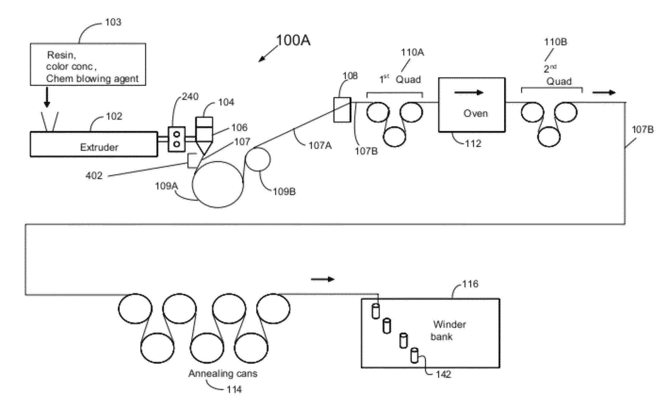
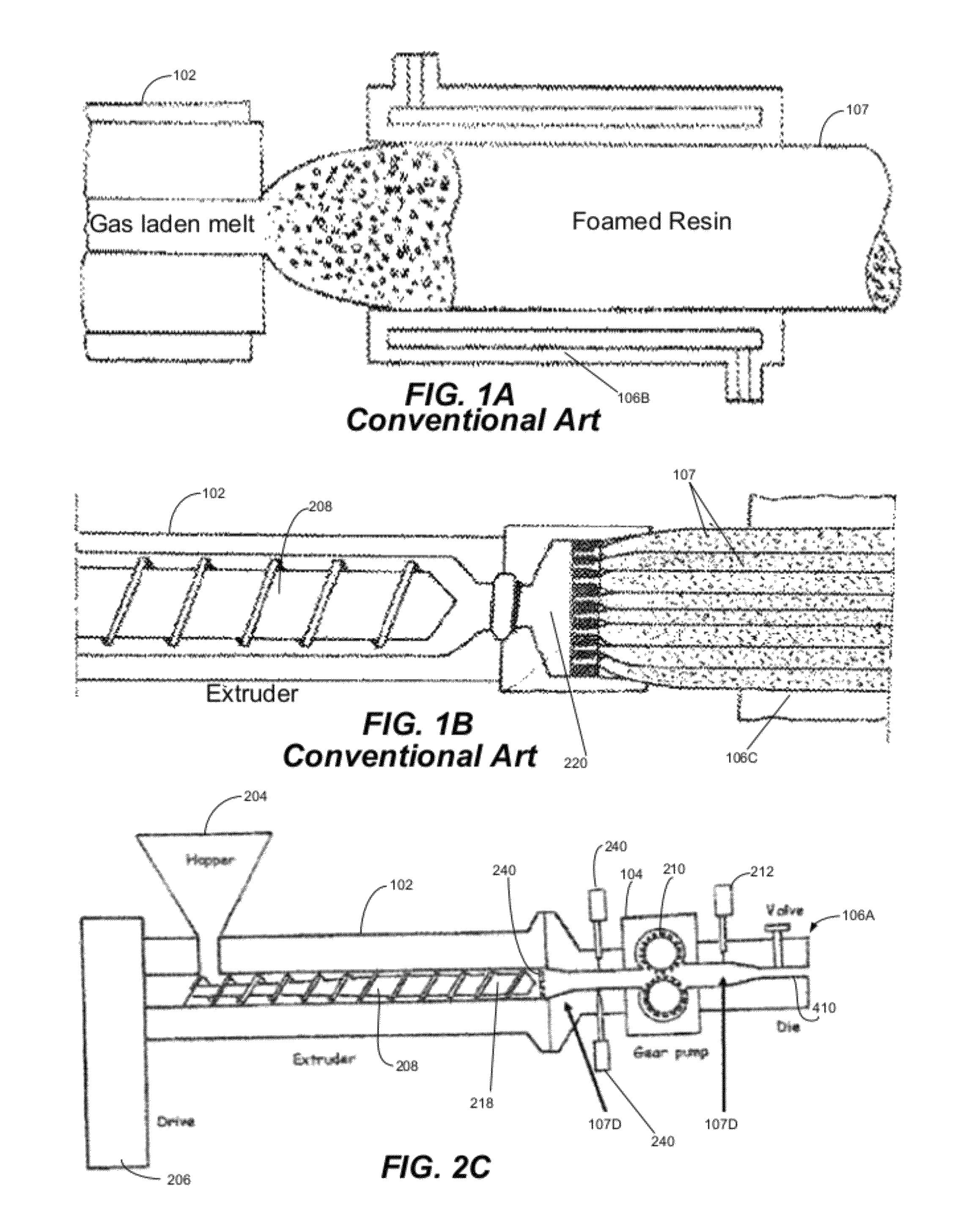
[0041]The inventive method and system can produce thin, lightly foamed tape at a speed that is much higher than is used for conventional foaming processes. Typical foamed, oriented tape dimensions are about 1.0 to about 4.0 mils thick when measured according to test method ASTM 3218, and 20 to 400 mils wide. In contrast to many extruded foam profiles, the tapes of the invention are not shaped by a calibrating device such as 106B in FIG. 1A or 106C in FIG. 1B, and the foamed sheet is not passed through a stack of polished rolls while still molten, as is commonly done when a foamed sheet is produced.
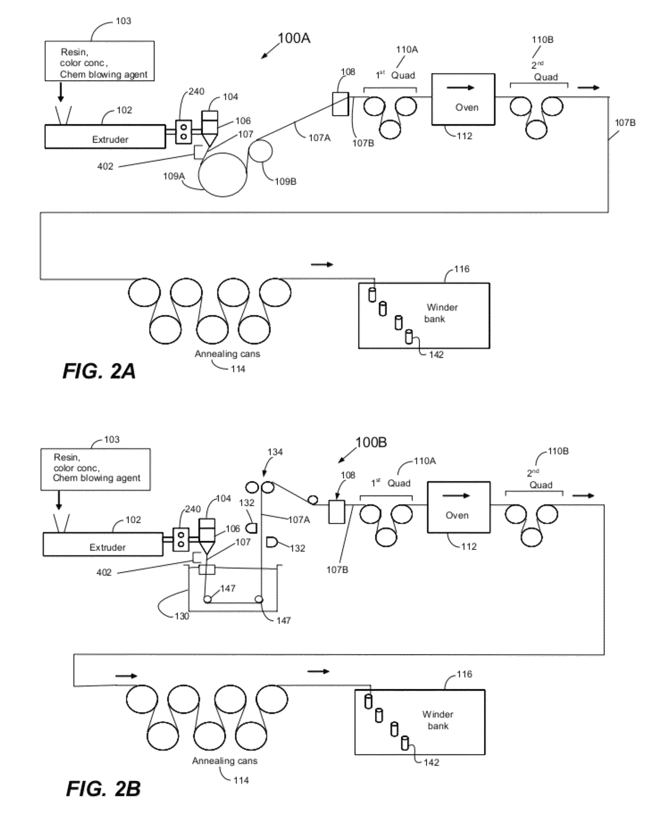
[0042]With the inventive system and method, the internal void content is not typically as high as what would be calculated if all the gas resulting from decomposition of the blowing agent were allowed to form a closed cell foam. This can be attributed to the high haul off speed, rapid cooling of the foamed sheet in contact with the cooling devices, such as a quench bath or chill roll, and the high surface to volume ratio of the thin, unoriented sheet prior to quenching. The tapes can have void contents between about 20 and about 150%. At least one surface has multiple longitudinal ridges that result from expansion of the entrained gaseous decomposition products. The tapes can be produced without extreme difficulty and have very good property profiles for the various applications described above. Those applications include, but are not limited to, carpet backings, geotextiles, packaging, housewrap, netting for bags or containers, netting for food stuffs, and insulation for wires.

Problems solved by technology

Often the strength of the starting tapes is diminished when they are woven into fabrics.
While the conventional art describes the advantages of foamed, oriented polypropylene tapes in the above applications, much of the conventional art does not articulate how these foamed tapes can be manufactured.
Most of the conventional art only describes the mechanical properties of the end products (i.e., the tapes and woven fabrics) and fails to provide any information on a sequence of specific steps and / or processes for producing such foamed, oriented tapes.
However, the conventional art does not provide a complete set of steps which would allow one of ordinary skill in the art to produce repeatable and accurate results for manufacturing foamed, oriented polyolefin tapes for carpet backings.
Specifically, the conventional art does not provide discrete steps that describe how to manufacture foamed, oriented polyolefin tapes economically and efficiently at high line speeds, such as speeds at or above 850 feet per minute.
While this is needed for thick section parts, it is very difficult to implement with thin sheets for tapes that are produced at faster extrusion speeds, since the opening (interior height dimension) within the calibrator for thin sheets would be very small, leading to frequent clogging and tearing of the foam sheet.
Consequently, the conventional processes of shaping a foamable extrudate, either by a calibrator or stack of smooth calendar rolls do not provide much useful information about how to make the thin, foamed tapes with ridged surfaces that are the end products of the inventive method and system.

Method used


Image

  • Method and system for manufacturing foamed polyolefin tapes at cost effective line speeds
  • Method and system for manufacturing foamed polyolefin tapes at cost effective line speeds
  • Method and system for manufacturing foamed polyolefin tapes at cost effective line speeds

Examples


example 1

Approximate Speed of about 1000 fpm for Producing Warp Yarn

[0189]A 4.5-inch single-screw extruder with a 28:1 L / D was charged with about 97.9 parts by weight of a polypropylene homopolymer resin with a MFR of about 3.5, about 1.6 parts of a beige pigment masterbatch (SCC 16234 for Standridge Color Corp). and about 1.5 parts of a chemical blowing agent masterbatch (Hydrocerol® 3034 from Clariant Masterbatch GmbH). The blowing agent masterbatch was about 16% active and based on a citric acid / bicarbonate mixture. The temperatures of extruder barrel zones increased from about 394° F. to about 464° F. progressively from the throat to the discharge port. The molten mixture was discharged under pressure into a transfer tube attached to four spinning heads, each of which contained a melt pump and a circular spinneret with 90 rectangular holes. The temperatures in the transfer tube, individual melt pumps on each spinning head, and each spinning head were maintained in the range of about 420 ...

example 2

Approximate Speed of about 875 fpm for Producing Fill Yarn

[0191]A 6-inch single-screw extruder with a 28:1 L / D was charged with about 97.1 parts by weight of a polypropylene homopolymer resin with a MFR of about 3.5, about 1.6 parts of a beige pigment masterbatch (SCC 16234 for Standridge Color Corp) and about 1.3 parts of a chemical blowing agent masterbatch (Hydrocerol® 3034 from Clariant USA). The blowing agent masterbatch was about 16% active and based on a citric acid / bicarbonate mixture. The temperatures of extruder barrel zones were about 420° F. in the first zone and about 441 to about 464° F. in barrel zones 2 through 6. The molten mixture was discharged at a temperature of about 450° F. under pressure into a transfer tube attached to a melt filter, melt pump and an 80-inch wide coathanger film die. The temperatures in the transfer tube, melt pump and die were maintained at about 450° F.

[0192]The pressure was about 3300 psi at the end of the extruder, about 2000 psi at the ...

example 3

Approximate Speed of about 1054 fpm for Producing Fill Yarn

[0194]A 6-inch single-screw extruder with a 28:1 L / D was charged with about 96.7 parts by weight of a polypropylene homopolymer resin with a MFR of about 3.5, about 1.6 parts of a beige pigment masterbatch (SCC 16234 for Standridge Color Corp). and about 1.7 parts of a chemical blowing agent masterbatch (Hydrocerol® 8697 from Clariant USA). The blowing agent masterbatch was about 12% active and based on a citric acid / bicarbonate mixture. The temperatures of extruder barrel zones were about 374° F. in the first zone and about 423 to about 482° F. in barrel zones 2 through 6. The molten mixture was discharged at a temperature of about 430° F. under pressure into a transfer tube attached to a melt filter, melt pump, and an 80-inch wide coathanger film die. The temperatures in the transfer tube and melt pump were about 430° F., and the temperature of the die was about 415° F.

[0195]The pressure was about 2550 psi at the end of th...


PUM

PropertyMeasurementUnit
thicknessaaaaaaaaaa
distanceaaaaaaaaaa
distanceaaaaaaaaaa

Abstract

Making foamed polyolefin tapes can include combining a polyolefin resin and a chemical blowing agent to form a mixture. This mixture can then be heated in an extruder to create a supersaturated solution of gas within the polyolefin resin. A cooling device can be positioned adjacent to a die at a set distance for receiving extruded resin and for allowing exposure of the extruded resin to ambient air between a die outlet and the cooling device. This predetermined distance or space between the cooling device and die outlet allows bubbles to grow in the extruded resin and to be shaped such that voids or empty spaces can be generated within the extruded polyolefin resin. The voids or empty spaces allow the formation of tapes which use less material but have adequate strength for various applications, such as for carpet backings, geotextiles, packaging, housewrap, bags, wire insulation, and reinforcement elements in concrete.

Description

STATEMENT REGARDING RELATED APPLICATIONS[0001]The present application claims priority to provisional patent application entitled, “Method and System for Manufacturing Foamed Polyolefin Tapes at Cost Effective Line Speeds,” filed on Nov. 1, 2007 and assigned U.S. Application Ser. No. 60 / 984,564, the entire contents of which are hereby incorporated by reference.FIELD OF INVENTION[0002]This invention generally relates to foamed, oriented tape yarns used in carpet backing, geotextiles, packaging, housewrap, and similar applications. More particularly, the invention relates to a high speed process for producing foamed, oriented polyolefin tapes for such applications.BACKGROUND OF THE INVENTION[0003]Oriented polyolefin tape yarns are commonly used in woven fabrics for applications such as carpet backing, geotextiles for soil stabilization and separation, and in coated fabrics such as housewrap, lumber wrap, and laminates for flexible packaging applications. In all these applications, the ...

Claims


Application Information

Patent Timeline
Patent Type & Authority Patents(United States)
IPC IPC(8): C08J9/06B29C48/05B29C48/90
CPCB29C44/5654C08J9/06C08J2201/03C08J2323/02B29C48/05B29C48/90B29C48/908
Inventor GARDNER, HUGH C.UESBECK, JOSEFRAKOVAC, ANDYCOMBIER, PHILIPPELUI, KAM
Owner PROPEX FURNISHING SOLUTIONS INC
Why Eureka
Try Eureka