
Method for accurately finding a physical location on an image bearing surface for toner images for optimal streak correction

a technology of image bearing surface and location method, which is applied in the direction of image enhancement, digital output to print units, instruments, etc., can solve the problems of affecting the quality of streak correction, and affecting the accuracy of toner image streak correction

Active Publication Date: 2012-08-28
XEROX CORP
View PDF10 Cites 1 Cited by
  • Summary
  • Abstract
  • Description
  • Claims
  • Application Information

AI Technical Summary

Problems solved by technology

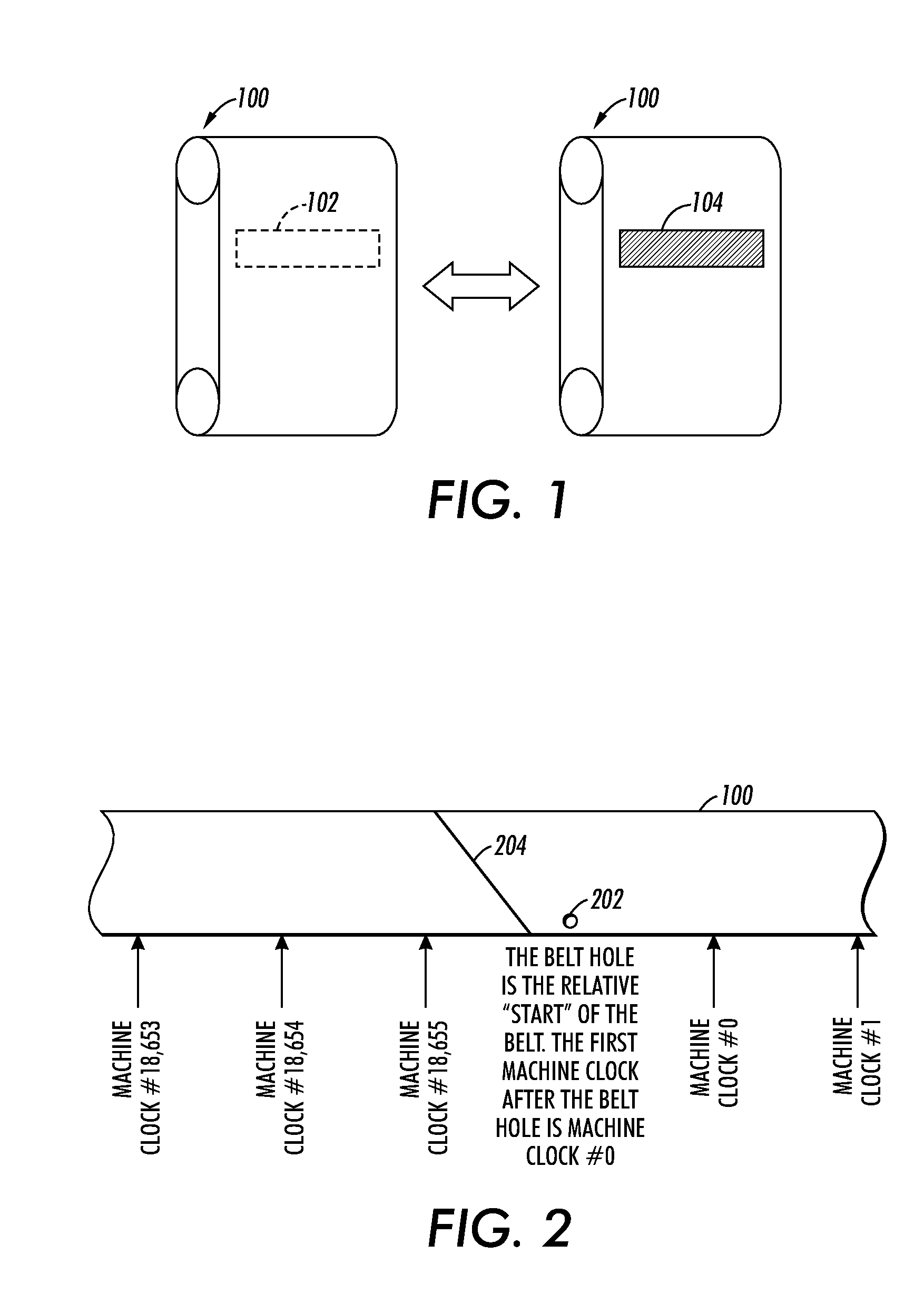
However, for various reasons, there can be a difference of up to several machine clock counts between what the offset is thought to be, and where the offset actually is.
This difference degrades the quality of the streak correction.
These start locations for calibrations and clean image bearing surface scans were determined by another subsystem, and transmitted to the image printing system, but this method of determining and transmitting the start locations for calibrations and clean image bearing surface scans is often not highly accurate or reliable.
Further, the regions on the image bearing surface that are used during calibration cannot be reliably identified by an exact machine clock signal because the machine clock and belt hole clock are asynchronous.

Method used


Image

  • Method for accurately finding a physical location on an image bearing surface for toner images for optimal streak correction
  • Method for accurately finding a physical location on an image bearing surface for toner images for optimal streak correction
  • Method for accurately finding a physical location on an image bearing surface for toner images for optimal streak correction

Examples


Embodiment Construction

[0016]A streak correction methodology in an image printing system comprises printing halftone toner images on an image bearing surface, scanning the halftone toner images with a full width array sensor, and then processing the scanned halftone toner images with a processor into a profile which is used to determine the amount of streak correction. The processing step includes normalizing the halftone toner image data between a black value and a white value. The white value generally represents a value of the image bearing surface before placing the halftone images and the black value generally represents a fixed constant. The white value is calculated by scanning the image bearing surface before printing the toner images, converting the scanned image bearing surface (i.e., before placing the toner images on the image bearing surface) into profiles, and storing these profiles in memory. These profiles are later used when the halftone toner images are being processed.

[0017]A section or...


PUM


Abstract

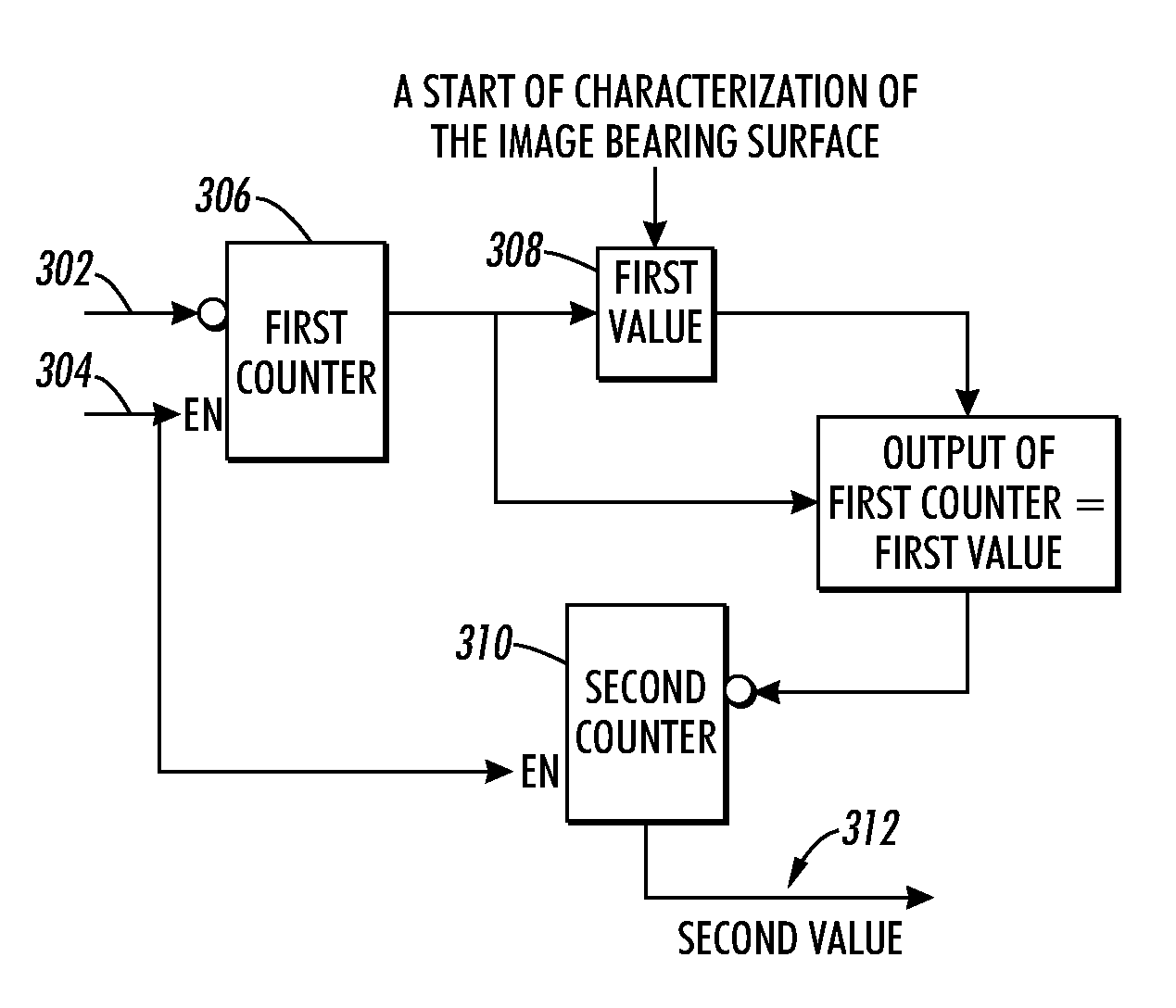
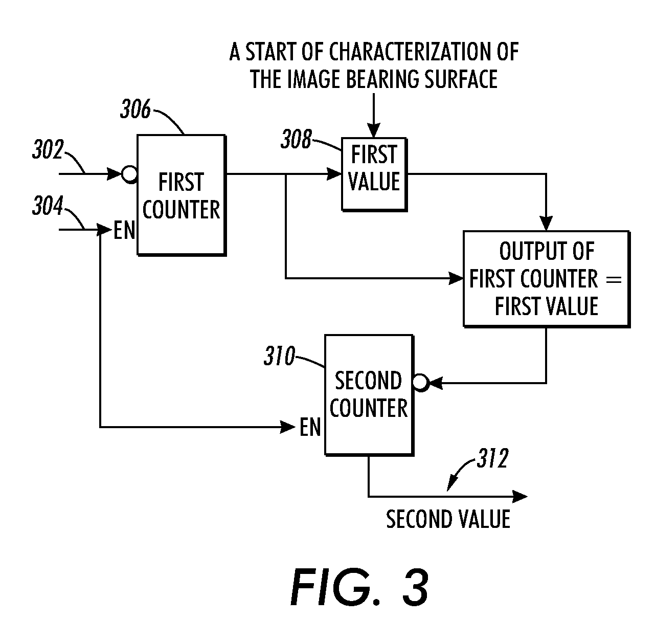
A method for determining a location on an image bearing surface of an image printing system where a toner image is to be printed is provided. The method comprises generating a first signal from a detector that is configured to detect a reference mark on the image bearing surface, and a second signal from a clock system that counts incremental movements of the image bearing surface, determining a first value that correlates the first signal and the second signal, where the first value corresponds to a value of the second signal at a start of characterization of the image bearing surface, and determining a second value using the first value, where the second value provides the location on the image bearing surface where the toner image is to be printed.

Description

BACKGROUND[0001]1. Field[0002]The present disclosure relates to a method and a system for determining a location on an image bearing surface of an image printing system where a toner image is to be printed.[0003]2. Description of Related Art[0004]For streak correction in an image printing system, it is important to know with as much certainty as possible where toner images are physically placed on an image bearing surface (e.g., a photoreceptor belt or drum) of the image printing system. One of the prior art approaches was to determine how many “machine clock” counts the toner images are offset from the belt hole. The term “machine clock” refers to a counter or other device that monitors the incremental movements of the belt. Each time a machine clock signal is counted, that indicates movement of the image bearing surface by the applicable increment. However, for various reasons, there can be a difference of up to several machine clock counts between what the offset is thought to be...

Claims


Application Information

Patent Timeline
Patent Type & Authority Patents(United States)
IPC IPC(8): G06K15/10G01D15/06G03G15/01
CPCG03G15/5033G03G15/0131G03G15/5054G03G2215/00037G03G2215/00059G03G2215/00759
Inventor HUEDEPOHL, RALPHCLINGERMAN, TERRI ACOY, GERALD L.
Owner XEROX CORP
Learn More