Supercharge Your Innovation With Domain-Expert AI Agents!

Transfer device with electrically conducting elastic member

a technology of transfer device and elastic member, which is applied in the direction of electrographic process apparatus, instruments, optics, etc., can solve the problems of difficult separation of transfer material from transfer drum, difficult control of each electrifier, and complicated apparatus configuration, so as to improve the transfer material and peeling improve the close contact properties of the transfer material, and improve the transfer material. the effect of transfer material

Inactive Publication Date: 2012-08-28
SEIKO EPSON CORP
View PDF5 Cites 2 Cited by
  • Summary
  • Abstract
  • Description
  • Claims
  • Application Information

AI Technical Summary

Benefits of technology

The invention provides a transfer device and an image forming apparatus that improve the transfer properties of a toner image onto an image carrier and ensure the separating of the transfer material from the transfer roller. The transfer device includes an electrically-conductive elastic member that supports a transfer material, a transfer material separating member that peels off the transfer material from the elastic member, a supporting member that supports both the elastic member and the transfer material separating member, and a transfer bias applying section that applies a transfer bias. The image forming apparatus includes an image carrier that supports a developed image, a transfer section, a transfer material transport section, and a fixing section. The technical effects of the invention include improved transfer properties and peel properties of the transfer material.

Problems solved by technology

But, in the image forming apparatus disclosed in JP-A-3-4241, it is necessary to dispose a plurality of electrifiers such as the electrifier for adsorption of the transfer material, the electrifier for transfer, and the electrifier for separating in the transfer drum, so that a configuration of the apparatus is complicated and control of each electrifier is also difficult.
Also, in the image forming apparatus disclosed in JP-T-2000-508280, since the transfer of the toner image to the transfer material is thermal transfer by heating and pressurizing, the adhesion properties of the transfer material with the toner image transferred thereto to the transfer drum becomes stronger, so that there is a problem that the separating of the transfer material from the transfer drum becomes difficult.

Method used


Image

  • Transfer device with electrically conducting elastic member
  • Transfer device with electrically conducting elastic member
  • Transfer device with electrically conducting elastic member

Examples


Embodiment Construction

[0035]Hereinafter, embodiments of the invention will be explained with reference to the drawings.

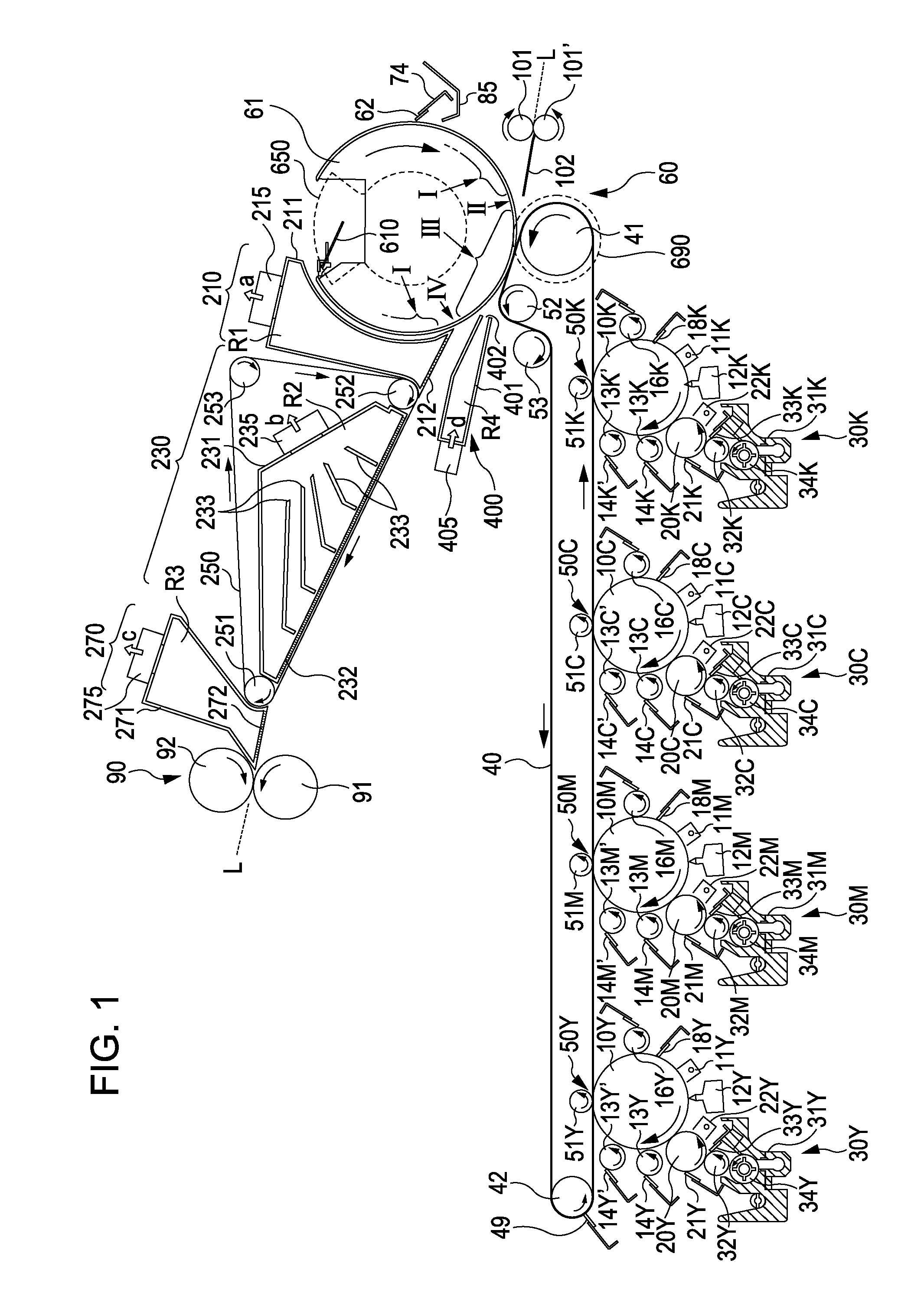
[0036]FIG. 1 is a view showing principal components constituting an image forming apparatus concerning an embodiment of the invention. With respect to an image forming section of each color, which is disposed at the central portion of the image forming apparatus, developing devices 30Y, 30M, 30C, and 30K are disposed at the lower portion of the image forming apparatus, and components such as a transfer belt 40, a secondary transfer section (secondary transfer unit) 60, and a fixing unit 90 are disposed at the upper portion of the image forming apparatus. In particular, due to a layout in which the fixing unit 90 is disposed above the transfer belt 40, the installation area of the whole image forming apparatus can be suppressed. In this embodiment, since a configuration is made such that a transfer material such as a paper, which has been subjected to secondary transfer at the secondary t...


PUM


Abstract

A transfer device includes: an electrically-conductive elastic member which carries a transfer material; a transfer material separating member which peels off the transfer material from the elastic member; a supporting member which has an elastic member supporting portion that supports the elastic member, and a separating member supporting portion that supports the transfer material separating member, and also, has electrically-conductive properties; and a transfer bias applying section which is electrically connected to the supporting member, thereby applying a transfer bias.

Description

BACKGROUND[0001]1. Technical Field[0002]The present invention relates to a transfer device of an electrophotographic system and an image forming apparatus.[0003]2. Related Art[0004]There is proposed an image forming apparatus which develops a latent image of an image carrier by a developing device, thereby obtaining a visualized image and is provided with a transfer device that directly transfers a toner image on the image carrier to a transfer material such as paper. Also, there is proposed an image forming apparatus which visualizes a latent image of an image carrier by a developing device, thereby obtaining a visualized image, transfers a toner image on the image carrier to an intermediate transfer medium that is constituted of a belt tensioned around a plurality of rollers, or a drum, and is provided with a transfer device that transfers a toner image on the intermediate transfer medium to a transfer material.[0005]In JP-A-3-4241, there is disclosed an image forming apparatus wh...

Claims


Application Information

Patent Timeline
Patent Type & Authority Patents(United States)
IPC IPC(8): G03G15/16
CPCG03G15/161G03G15/1685G03G15/657G03G15/162G03G2215/1619
Inventor KAMIJO, KOICHICHIBA, SATOSHI
Owner SEIKO EPSON CORP
Features
  • R&D
  • Intellectual Property
  • Life Sciences
  • Materials
  • Tech Scout
  • Unparalleled Data Quality
  • Higher Quality Content
  • 60% Fewer Hallucinations
Learn More