Image forming apparatus that detects image shift in the main scanning direction without wasting toner

a technology of image forming apparatus and main scanning direction, which is applied in the direction of electrographic process apparatus, instruments, optics, etc., can solve the problems of inability to detect color shift in the main scanning direction at the same time, inability to perfectly superimpose toner images in the respective different colors, waste of toner, etc., and achieve the effect of reducing running costs

Inactive Publication Date: 2012-09-11
CANON KK
View PDF5 Cites 1 Cited by
  • Summary
  • Abstract
  • Description
  • Claims
  • Application Information

AI Technical Summary

Benefits of technology

[0012]The present invention provides an image forming apparatus which is capable of detecting the direction and amount of image shift in the main scanning direction without wasting toner, to thereby provide higher-quality images with reduced running costs.
[0017]According to the present invention, it is possible to clearly grasp objects to be controlled, by detecting the direction and amount of image shift simultaneously in the main scanning direction and in the sub scanning direction without wasting toner, separately in each image forming unit, to thereby obtain a higher-quality image.

Problems solved by technology

However, when the speed of rotation of the photosensitive drum or the intermediate transfer belt changes due to insufficient mechanical accuracy or the like, causing a change in the positional relationship in the transfer position of each color between the photosensitive drum and the intermediate transfer belt, toner images in the respective different colors cannot be perfectly superimposed one upon another.
However, it is required to use toner to form the position detection marks, which results in waste of toner.
However, in the method disclosed in Japanese Patent Laid-Open Publication No. 2001-83856, only color shift in the sub scanning direction is detected, but color shift in the main scanning direction cannot be detected at the same time.
Therefore, it is impossible to correct color shift in the main scanning direction.

Method used


Image

  • Image forming apparatus that detects image shift in the main scanning direction without wasting toner
  • Image forming apparatus that detects image shift in the main scanning direction without wasting toner
  • Image forming apparatus that detects image shift in the main scanning direction without wasting toner

Examples


first embodiment

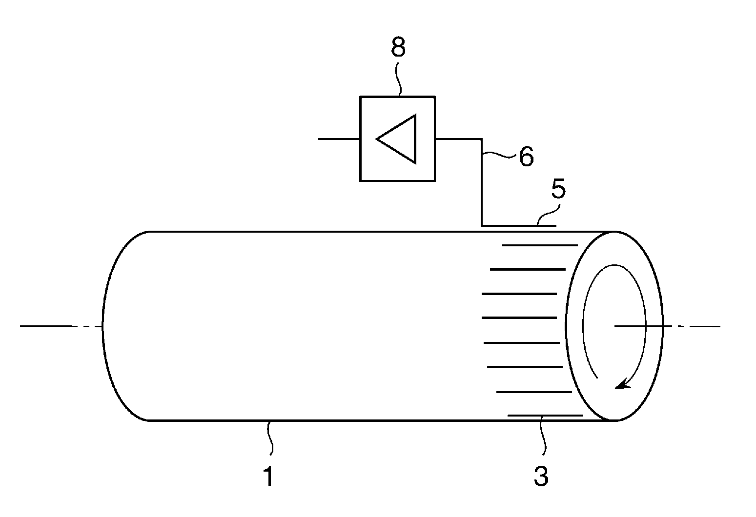
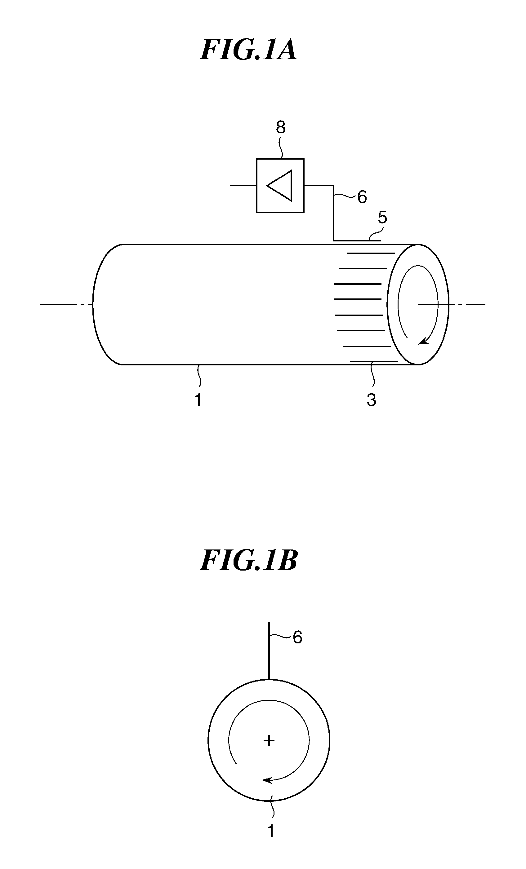
[0061]FIGS. 1A and 1B to 4A and 4B and FIGS. 30 to 40 are views and diagrams useful in explaining an image forming apparatus according to the present invention. FIG. 30 is a front view of essential parts of the image forming apparatus, and FIG. 31 is a perspective view of the essential parts of the same. FIGS. 32 and 33 are side views of a first image forming unit and a second image forming unit, as viewed from upstream in a belt conveying direction. FIGS. 34 and 35 are views of a photosensitive drum, an intermediate transfer belt and a sensor in the second image forming unit, which are useful in explaining details of the arrangement thereof. It should be noted that a plurality of members or components denoted by respective reference numerals formed by a same numeral and respective different alphabetical suffixes are collectively denoted by the numeral, as deemed appropriate.

[0062]Conventionally, in a tandem image forming apparatus, four or more photosensitive drums 1a, 1b, 1c, and ...

second embodiment

[0113]FIGS. 5A and 5B are views showing the positional relationship between an electrostatic latent image line, a conductor, and an image carrier in an image forming apparatus according to the present invention. FIG. 5A is a front perspective view, and FIG. 5B a side view.

[0114]As shown in FIGS. 5A and 5B, the present embodiment is distinguished from the first embodiment by the shape of each electrostatic latent image line 7 and that of a conductor (electrostatic latent image scale reading sensor) 9. In a case where the resolution of the image forming apparatus is set to 600 dpi, each of the electrostatic latent image lines 7 is written as a dotted line formed by dots (each of 42.3 μm) and spaces (each of 42.3 μm). In short, the electrostatic latent image line 7 is formed by a dotted line with a dot pitch approximately corresponding to the resolution of the image forming apparatus.

[0115]Further, the conductor 9 has a comb-teeth shape conforming to the dot pitch of the electrostatic ...

third embodiment

[0129]FIG. 8 is a view of conductors of an image forming apparatus according to the present invention. FIG. 9 is a side view of parts of the image forming apparatus, essential for electrostatic latent image scale reading.

[0130]In the present embodiment, two kinds of conductors 9 and 13 are provided, as shown in FIG. 8, whereby a circuit is formed in which an output signal obtained from the conductor 13 is inverted by an inverter 100 to be added to an output signal from the conductor 9 by an adder 101. The conductor 13 is comprised of a comb tooth parts 14 and a comb teeth support portion 15.

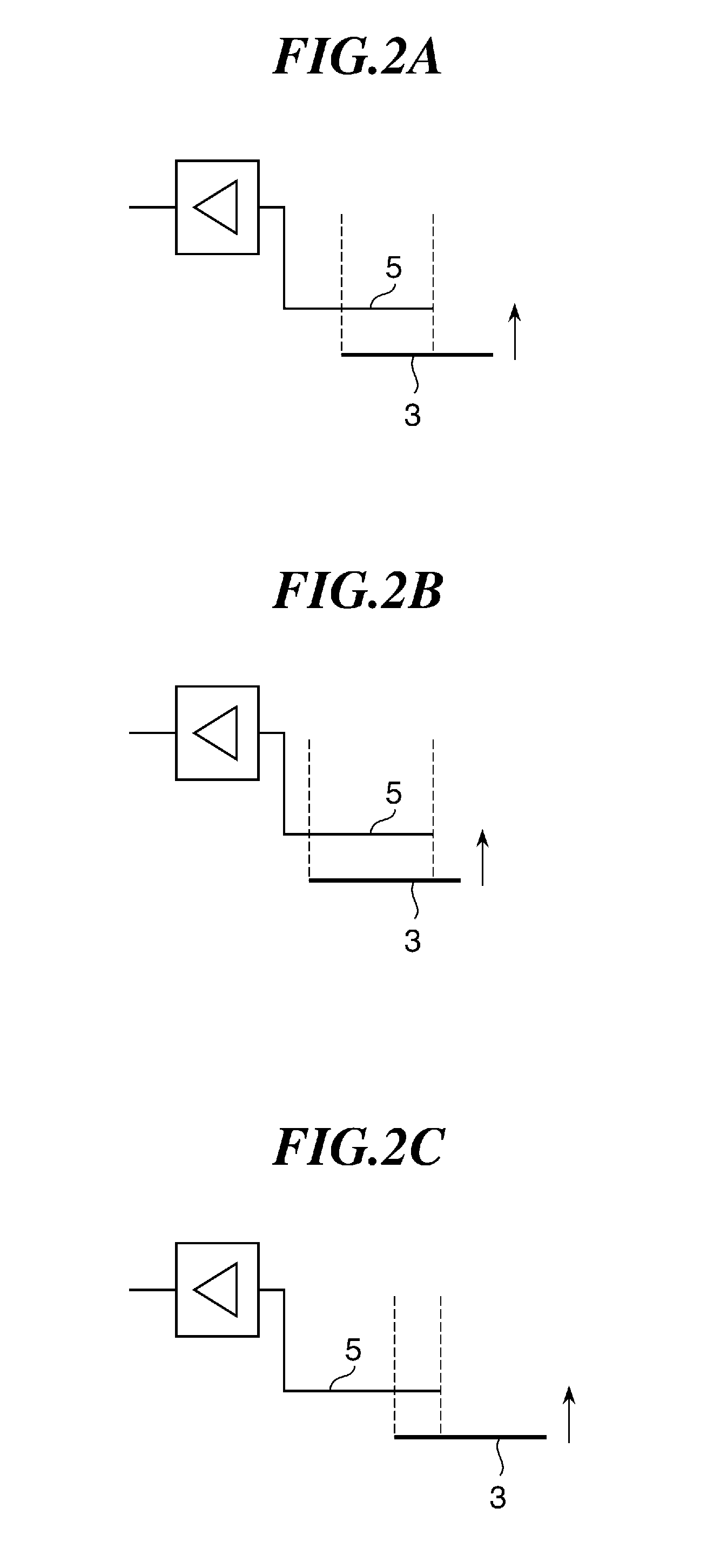
[0131]To be more specific, FIGS. 10A to 10C are views showing the positional relationship between the electrostatic latent image line 7 and the conductors 9 and 13, in which FIG. 10A illustrates a case where the electrostatic latent image line 7 is not shifted in the main scanning direction, FIG. 10B illustrates a case where the electrostatic latent image line 7 is shifted leftward, and FIG. 10C ...


PUM


Abstract

An image forming apparatus which is capable of detecting the direction and amount of an image shift in the main scanning direction without wasting toner, to thereby provide a higher-quality image with reduced running costs. A conductor is disposed such that the conductor partially overlaps an electrostatic latent image line formed on a photosensitive drum in a manner extending in a main scanning direction of the photosensitive drum, while moving relative to the electrostatic latent image line. The conductor generates induced current by the relative motion. An image shift in the main scanning direction is detected based on a result of measurement of the induced current generated by the conductor.

Description

BACKGROUND OF THE INVENTION[0001]1. Field of the Invention[0002]The present invention relates to an image forming apparatus for forming an image on a sheet, and more particularly to an image forming apparatus characterized by a color shift detection technique.[0003]2. Description of the Related Art[0004]A conventional electrophotographic color image forming apparatus has a photosensitive drum for carrying toner images and sequentially transfers the toner images in respective different colors onto an intermediate transfer belt or a sheet held on a conveyor belt to thereby form a color image.[0005]However, when the speed of rotation of the photosensitive drum or the intermediate transfer belt changes due to insufficient mechanical accuracy or the like, causing a change in the positional relationship in the transfer position of each color between the photosensitive drum and the intermediate transfer belt, toner images in the respective different colors cannot be perfectly superimposed ...

Claims


Application Information

Patent Timeline
Patent Type & Authority Patents(United States)
IPC IPC(8): G03G15/01
CPCG03G15/5033G03G15/5037
Inventor MIZUTANI, YURIOKUMURA, ICHIROHAYASHI, ISAO
Owner CANON KK
Why Eureka
Try Eureka