Hand tool articulating apparatus with offset handle
What is Al technical title?
Al technical title is built by PatSnap Al team. It summarizes the technical point description of the patent document.
a technology of articulating apparatus and hand tool, applied in the field of clamps, can solve the problems of difficult to achieve desired gripping strength, awkward use, cumbersome use, etc., and achieve the effect of maximizing the clamping for
Active Publication Date: 2012-09-25
DR SLICK
View PDF49 Cites 4 Cited by
Summary
Abstract
Description
Claims
Application Information
AI Technical Summary
This helps you quickly interpret patents by identifying the three key elements:
Problems solved by technology
Method used
Benefits of technology
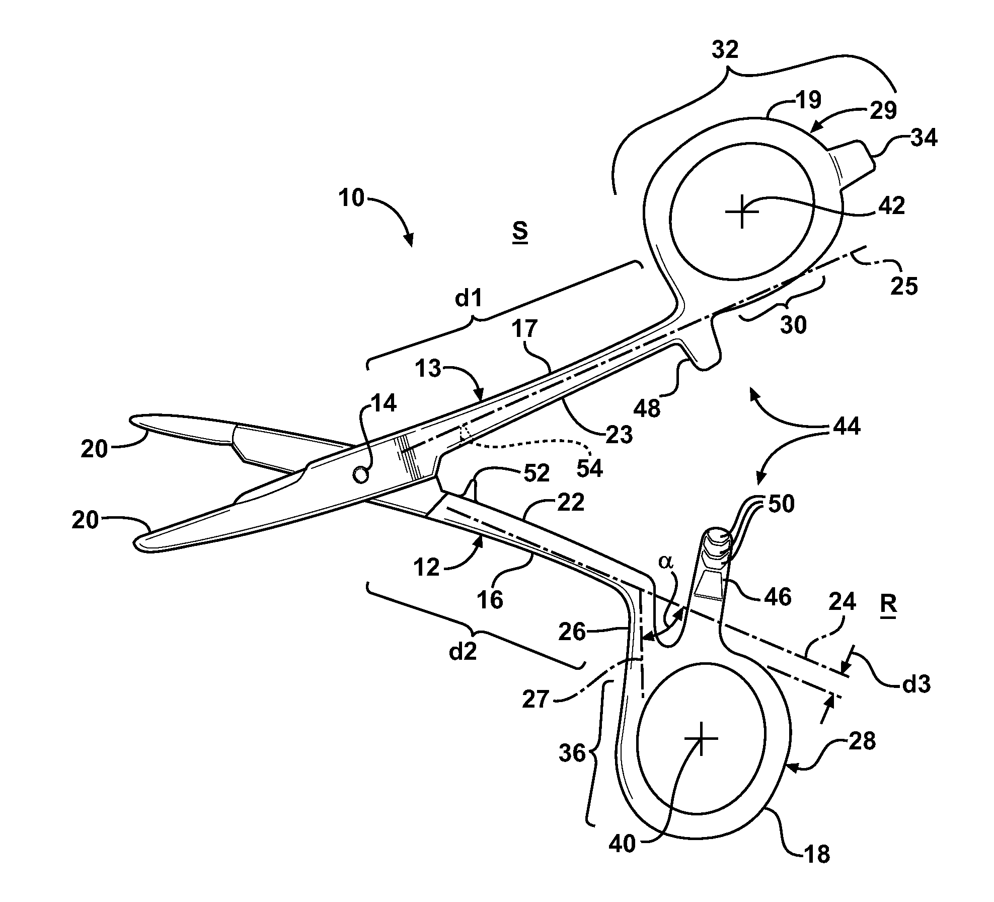
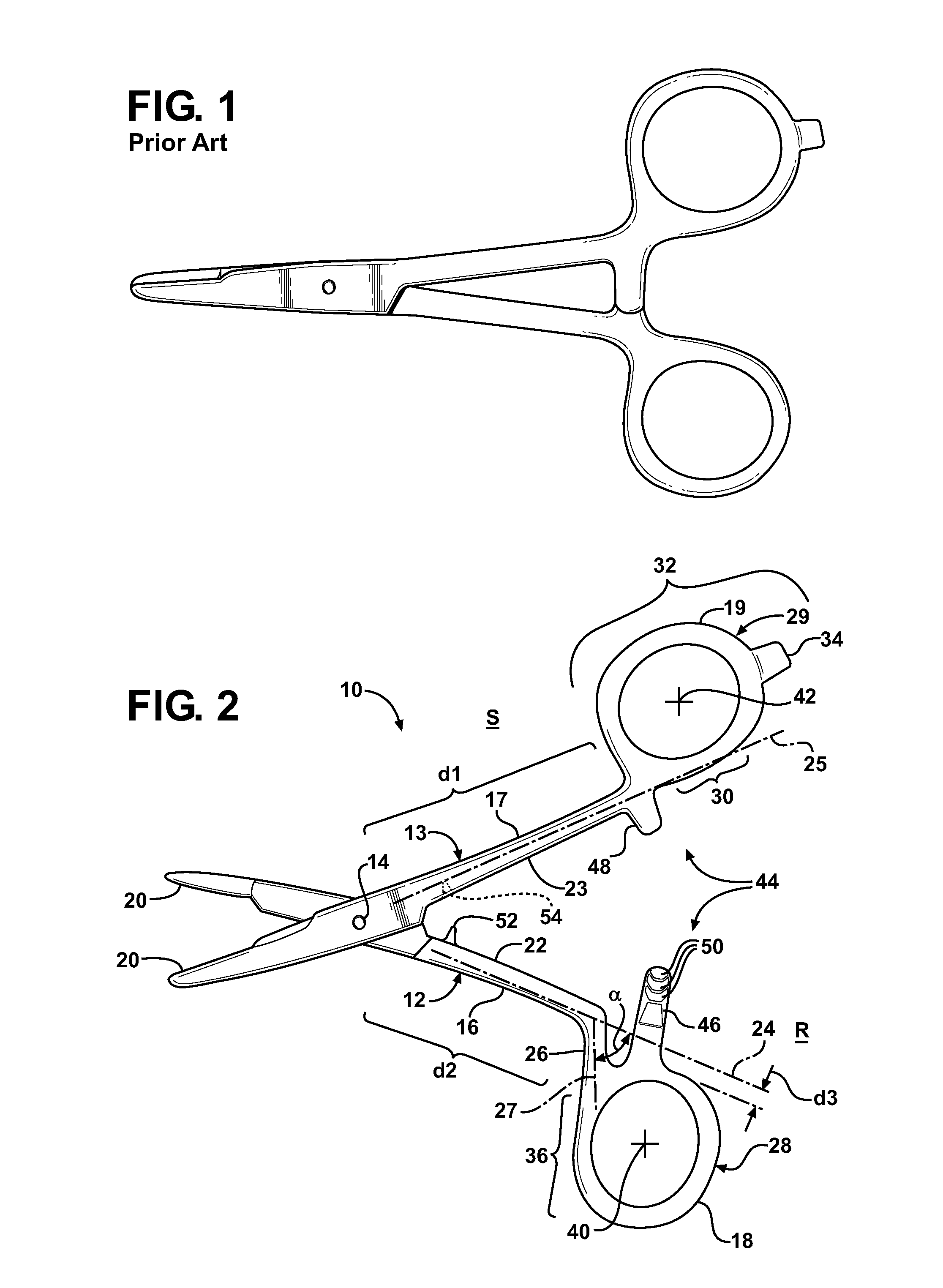
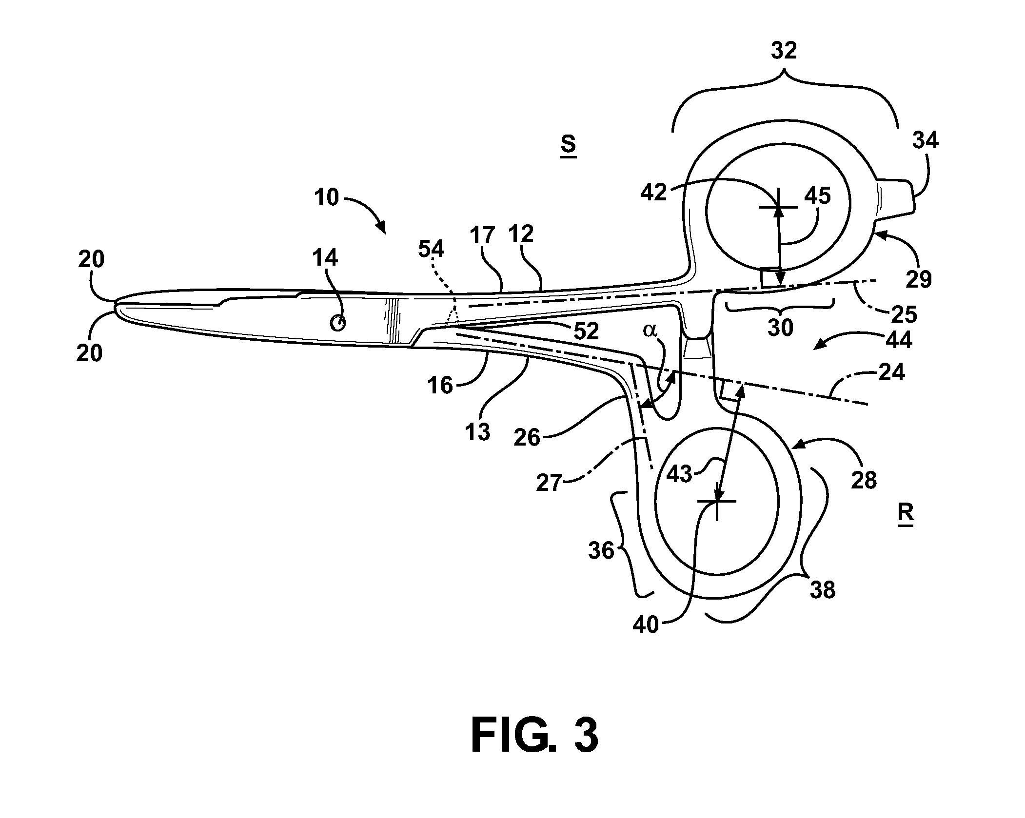
[0007]An articulating apparatus has a pair of elongate members coupled for articulation about a pivot axis. Each elongate member has a clamping jaw on one side of the pivot axis and an arm extending to a handle on the other side of the pivot axis. One of the arms extends from the pivot axis along a first axis over a first distance to a first loop extending outwardly from the first axis and away from the other of the arms. The other of the arms has a first portion and a second portion. The first portion extends along a second axis from the pivot axis a shorter distance than the one arm. The second portion extends inclined to the second axis along a third axis away from the one arm to a second loop. The second loop extends outwardly from the third axis away from the pivot axis. As such, the first and second loops are configured for ergonomic use and provide an ability to maximize a clamping force applied by the clamping jaws.
Problems solved by technology
Although these clamps are useful, they can prove awkward or cumbersome in use, given their unnatural configuration.
In additional, the desired gripping strength can be difficult to attain due to the user's hands being positioned unnaturally while applying a clamping force via the symmetrically oriented handles.
Method used
Image
Click on the blue label to locate the original text in one second.
Reading with bidirectional positioning of images and text.
Examples
Embodiment Construction
[0013]Referring in more detail to the drawings, FIGS. 2 and 3 illustrate an articulating apparatus 10, represented here, by way of example and without limitation, as a clamp constructed in accordance with one aspect of the invention for gripping objects, such as fishing hooks, fishing line, sutures, or blood vessels, such as in a surgical procedure, by way of example and without limitation. The articulating apparatus 10 can take other constructions in accordance with the invention, such as scissors, pliers and other assorted hand operated tools for use in fishing, medical and hobby industries, for example. Hereafter, the articulating apparatus in referred to as “clamp” for sake of conciseness. The clamp 10 has a pair of elongate members 12, 13 coupled to one another for articulated, pivoting movement relative to one another about a pivot axis 14. The elongate members 12, 13 each have a respective arm portion, referred to hereafter as arms 16, 17 and a respective handle portion, refe...
PUM
Abstract
A hand tool articulating apparatus has a pair of elongate members coupled for articulation about a pivot axis. Each elongate member has a clamping jaw on one side of the pivot axis and an arm extending to a handle on the other side of the pivot axis. One of the arms extends from the pivot axis along a first axis over a first distance to a first loop extending outwardly from the first axis and away from the other of the arms. The other of the arms has a first portion and a second portion. The first portion extends along a second axis from the pivot axis a shorter distance than the one arm. The second portion extends inclined to the second axis along a third axis away from the one arm to a second loop. The second loop extends outwardly from the third axis away from the pivot axis.
Description
CROSS-REFERENCE TO RELATED APPLICATION[0001]This application claims the benefit of U.S. Provisional Application Ser. No. 61 / 096,474, filed Sep. 12, 2008, which is incorporated herein by reference in its entirety.BACKGROUND OF THE INVENTION[0002]1. Technical Field[0003]This invention relates generally to clamps, and more particularly clamps used to squeeze, cut, clamp, grip, crush, or squeeze, such as pliers, scissors, forceps, nut crackers, for example, used in fields of fishing, mechanics, and the medical field, for example.[0004]2. Related Art[0005]Clamps are commonly used to grip objects to facilitate manipulating the object being gripped. For example, forceps are commonly used in fishing, particularly in fly fishing, wherein very fine fishing line often needs to be gripped. In addition, the forceps are commonly used to crush barbs on hooks, for removing hooks from fish, and for tying knots. It is also common practice to use forceps in medical procedures, such as in surgery, to g...
Claims
Application Information
Patent Timeline
Application Date:The date an application was filed.
Publication Date:The date a patent or application was officially published.
First Publication Date:The earliest publication date of a patent with the same application number.
Issue Date:Publication date of the patent grant document.
PCT Entry Date:The Entry date of PCT National Phase.
Estimated Expiry Date:The statutory expiry date of a patent right according to the Patent Law, and it is the longest term of protection that the patent right can achieve without the termination of the patent right due to other reasons(Term extension factor has been taken into account ).
Invalid Date:Actual expiry date is based on effective date or publication date of legal transaction data of invalid patent.