
Rapid clamping system

a clamping system and clamping technology, applied in the direction of metal-working holders, large fixed members, supporters, etc., can solve the problems of high pressure in the pressure chamber, problematic use of balls, etc., and achieve the effect of the same width

Active Publication Date: 2011-11-29
SCHUNK GMBH & CO KG SPANN UND GREIFTECHN
View PDF8 Cites 7 Cited by
  • Summary
  • Abstract
  • Description
  • Claims
  • Application Information

AI Technical Summary

Benefits of technology

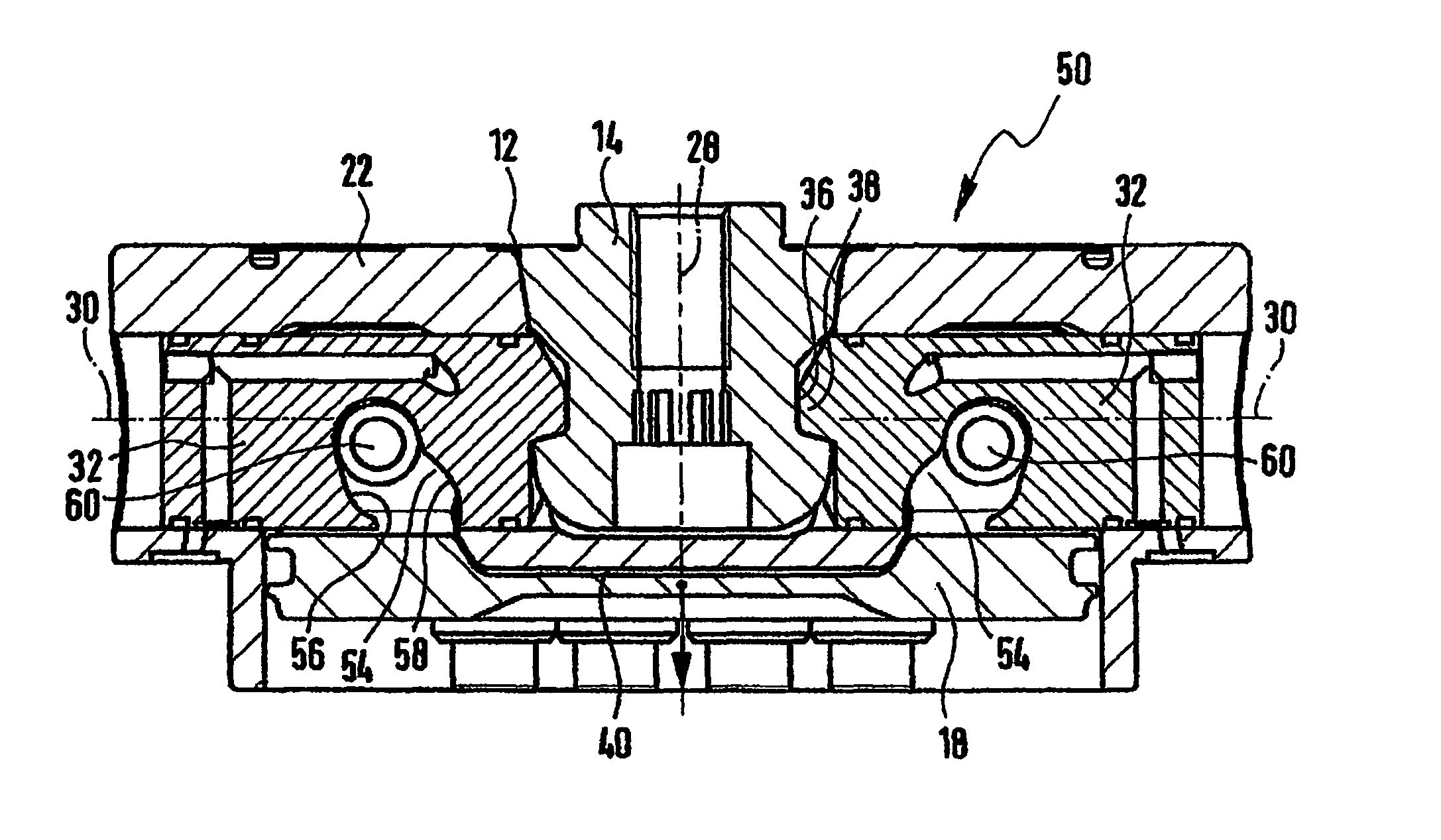
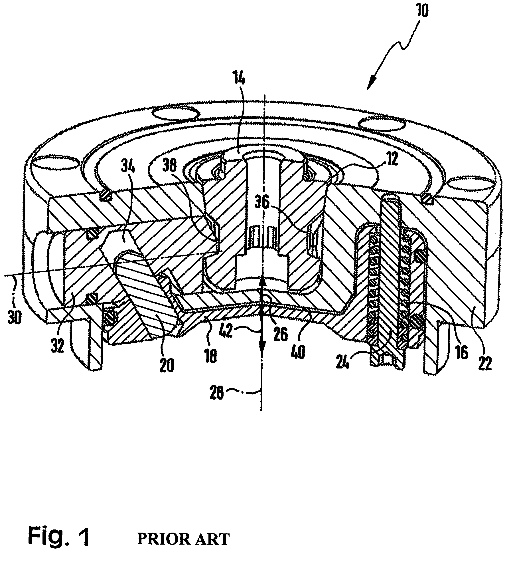
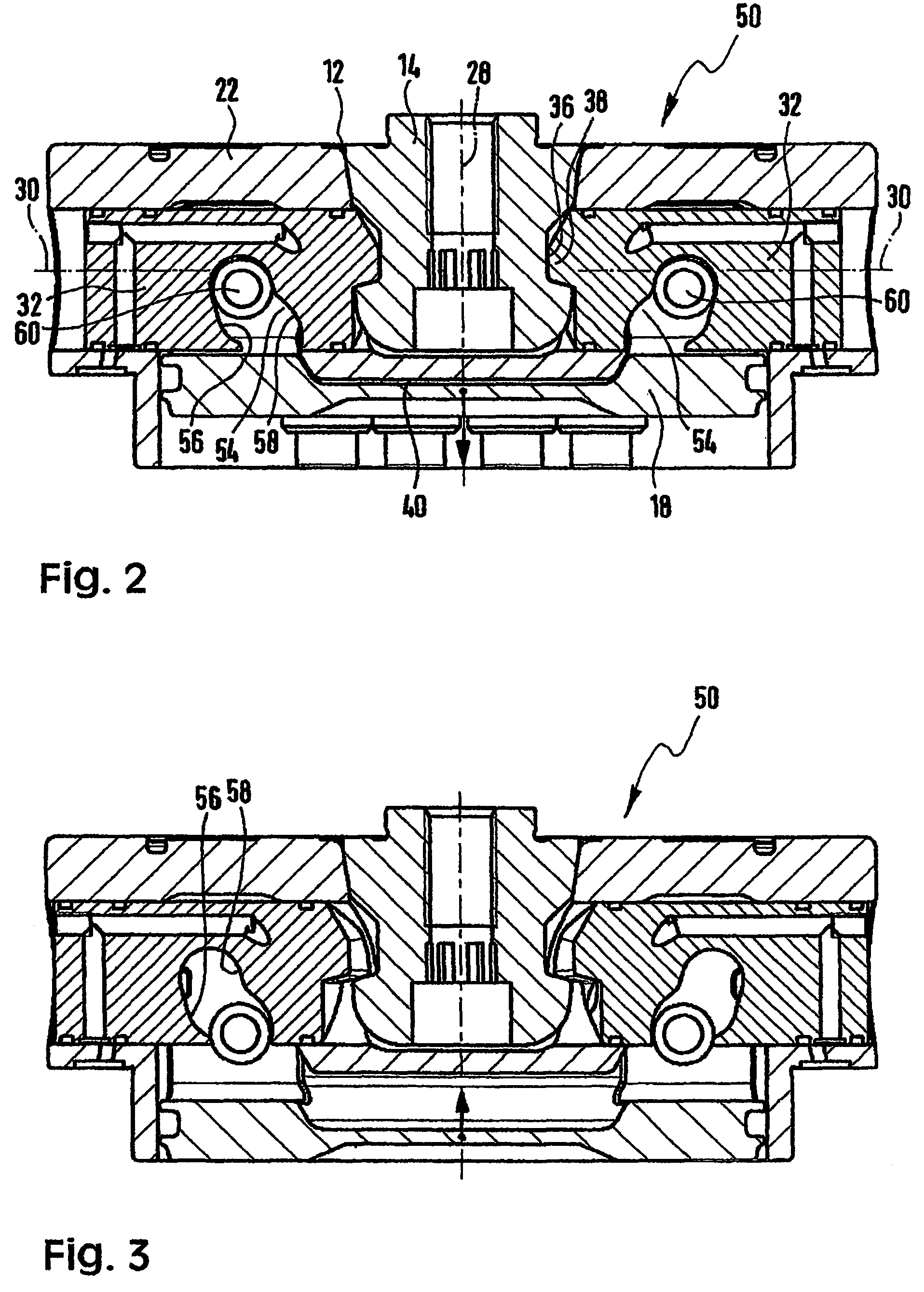
[0011]This object is achieved by the above-mentioned rapid clamping system in that the inclined guide has an irregular guide contour with different angles of inclination relative to the piston axis to obtain different transmission ratios. The inventive rapid clamping system consequently differs from the prior art of FIG. 1 in that the actuator and the inclined guide do not provide a linear transmission ratio, but an optimized transmission ratio due to the irregular guide contour in order to maximize the clamping force in the locking position.
[0012]It must thereby be taken into consideration that, due to their extension, the springs to be used to load the piston on one side regularly provide a smaller force in their locking position than in the unlocking position in which the springs are pretensioned to a larger degree. This path-dependent spring force of the springs results, in particular, from the relatively short length of the springs. The inventive rapid clamping system can e.g. compensate for the path-dependent spring force of the springs to be used, such that the clamping force can be optimized, in particular, in the locking position. Depending on the angle of inclination of the guide contour to be provided, the transmission ratio of the motion of the actuator can be varied to move the clamping bolt. However, high tilting moments can be transmitted due to provision of the clamping bolt.
[0016]The rapid stroke sections thereby advantageously have an angle of inclination in a range between 30° and 60° and, in particular, in a range between 40° and 50° and / or the power stroke sections have an angle of inclination in a range from more than 0° to 30° and, in particular, in a range between 15° and 25°. With rapid stroke sections of 40° to 50° it has turned out that a sufficient amount of force can be provided for moving the adjusting slide, thereby correspondingly increasing the velocity of the adjusting slide. For angles of inclination in a range between 15 and 25°, it has turned out that, in particular with decreasing spring force, the force can be correspondingly increased to a sufficient extent.
[0017]With particular advantage, the guide contour is matched to the characteristics of the springs in such a fashion that the angles of inclination are smaller when the spring force decreases, as mentioned above.
[0020]In accordance with the invention, the inclined guide may be designed as an inclined guide groove which extends transversely to the axis of motion of the clamping bolt, wherein the guide contour or the crank sections are formed by the opposite groove walls. In this respect, the actuator may be designed as a cylinder pin which is disposed on the piston and extends transversely to the axis of motion of the clamping bolt. The cylinder pin thereby advantageously has the same width or is wider than the guide groove, such that the forces can be transmitted over a large area.

Problems solved by technology

This is disadvantageous in that, for opening the rapid clamping system, a correspondingly high pressure must be provided in the pressure chamber 40.
However, the use of balls is problematic, since it is not possible to transfer high tilting moments of the clamping pin in the clamping receptacle.
Due to the spherical surface of the balls, these tend not to prevent an undesired deflection of the clamping pin out of the clamping receptacle.

Method used


Image

  • Rapid clamping system
  • Rapid clamping system
  • Rapid clamping system

Examples


Embodiment Construction

[0029]The construction of the inventive rapid clamping system 50 shown in the figures corresponds substantially to the rapid locking system 10 of FIG. 1. The corresponding components therefore have corresponding reference numerals.

[0030]Substantial differences between the inventive rapid clamping system 50 and the conventional rapid clamping system 10 are the design of the inclined guide and of the actuators. In the inventive rapid clamping system 50, the inclined guides 52 provided on the clamping bolts 32 have an irregular guide contour 54 with different angles of inclination relative to the piston axis 28 to obtain different transmission ratios. The respective guide contour 54 provides two opposite crank sections 56 and 58 which do not extend parallel to each other, wherein the actuators, which are designed as cylinder pins 60 which are rigidly disposed on the pistons 18, move along the crank sections 54 to reach the locking position, and move along the crank sections 56 to reach...


PUM


Abstract

The invention relates to a rapid clamping system (50), comprising a clamping housing (12), with a piston (18) acted on from one side by springs (15) and which may be pressurised from the other side, with an actuator (60) arranged on the piston (18) to follow the piston movement, with at least one clamping bolt (32) arranged to be displaced perpendicular to the piston axis (28), in a working coupling acting in both directions of displacement with the actuator (60) by means of an inclined guide (52), whereby, with the springs (16) extended, the clamping bolt (32) takes up a locking position for locking a clamping pin (14) which may be introduced in the clamping housing (12) and which adopts an unlocking position for removal of the clamping pin (14) on corresponding pressurization of the piston (18). The invention is characterized in that the inclined guide (52) has an irregular guide contour (54) with varying angles of inclination (α, β, γ, δ) relative to the piston axis (28) to achieve varying translation ratios.

Description

[0001]This application is the national stage of PCT / EP2006 / 002796 filed on Mar. 28, 2006 and also claims Paris Convention priority of EP 05 007 129.9 filed on Mar. 31, 2005.BACKGROUND OF THE INVENTION[0002]The invention concerns a rapid clamping system with a clamping receptacle, comprising a piston which is loaded from one side by springs and may be pressurized from the other side, an actuator arranged on the piston to follow the piston movement, at least one clamping bolt arranged to be displaced, in particular, at least substantially perpendicular to the piston axis and motionally coupled to the actuator in both directions of motion via an inclined guide on the clamping bolt side, wherein, with the springs extended, the clamping bolt assumes a locking position for locking a clamping pin which may be introduced in the clamping receptacle and which adopts an unlocking position for removal of the clamping pin when the piston is pressurized.[0003]The Assignee distributes rapid clampi...

Claims


Application Information

Patent Timeline
IPC IPC(8): B23B31/177
CPCB23Q1/0072Y10T279/1973Y10T279/1033Y10T279/1291
Inventor GROSS, JOHANNSEILER, HELMUT
Owner SCHUNK GMBH & CO KG SPANN UND GREIFTECHN
Learn More