Multistage hydraulic mechanical garbage incinerator

A technology of waste incinerator and hydraulic machinery, which is applied to incinerators, inclined grate, grate, etc., can solve problems such as affecting production operation, uneven distribution, wear of turning grate pieces and side wall grate pieces, etc., and achieves improvement. Combustion effect, uniform distribution of garbage, solving the effect of frequent derailment

Active Publication Date: 2012-07-25
EVERBRIGHT ENVIRONMENTAL PROTECTION TECHCAL DEV BEIJING +2
View PDF6 Cites 6 Cited by
  • Summary
  • Abstract
  • Description
  • Claims
  • Application Information

AI Technical Summary

Problems solved by technology

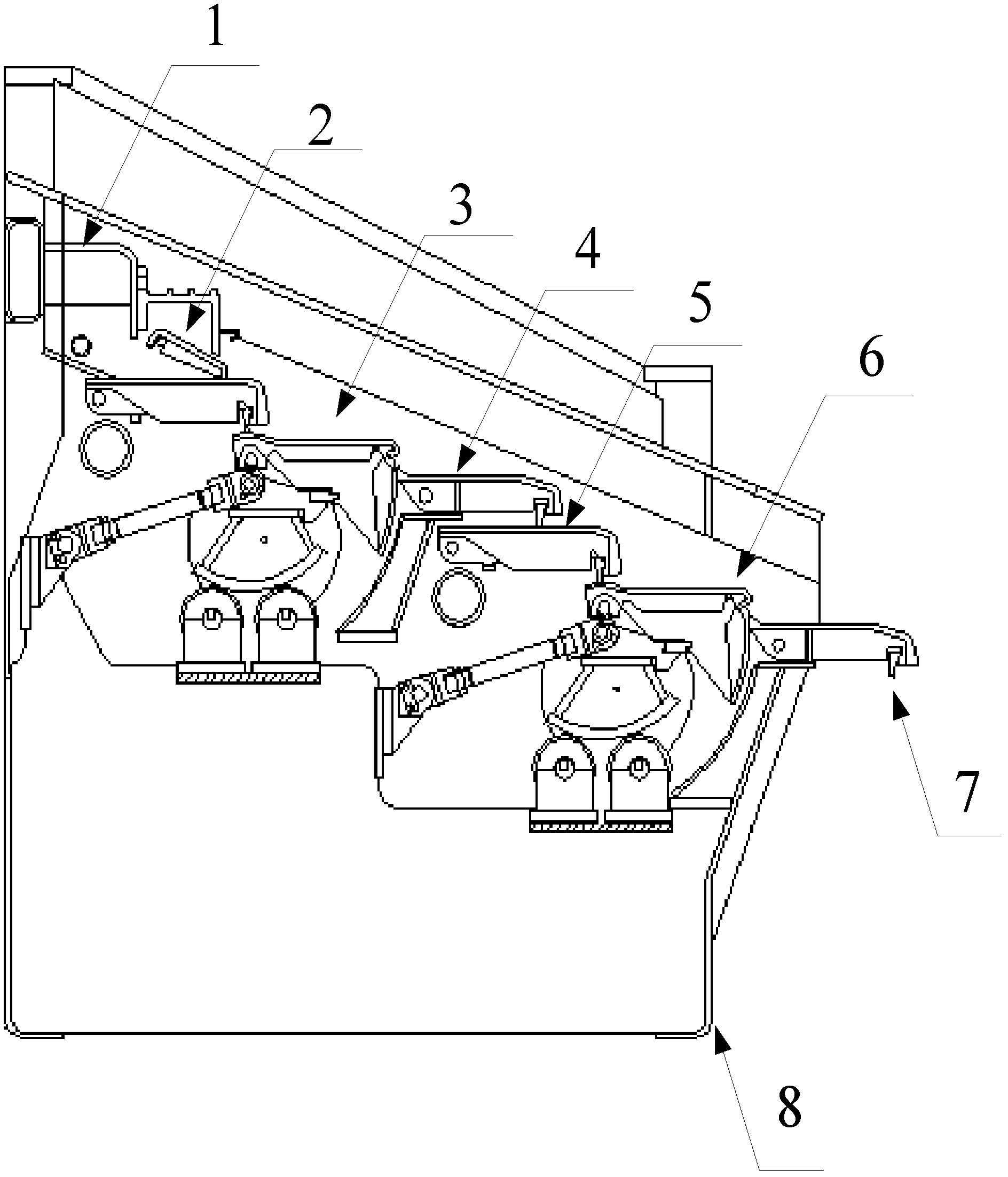
[0005] 1) Since the above-mentioned fire grate is arranged longitudinally as a whole, it is composed of four rows of fire grate units arranged side by side in the width direction. There is space for the hydraulic drive device in the middle part, and the structure of the grate itself is relatively compact. The space in the middle is small, which causes the heat transfer from the furnace to accumulate in this part, and the temperature rises. According to operating experience, basically The temperature is above 100°C, and the oil pipes of the existing incinerator grate hydraulic drive device mostly adopt a pipe joint connection structure. The excessively high temperature at the junction of the two driving shafts in the middle of the grate will cause the above-mentioned incinerator grate oil cylinder sealing ring to age. Frequent oil leakage may even cause fires, making operation more difficult
[0006] 2) In the prior art, the feeding trolley of the feeding grate of the domestic waste incinerator often has the tail of the trolley tilted too much during the process of pushing the material forward, causing the trolley to be stuck and unable to push the material normally and fall back. The trolley is pulled back to the initial position, which brings many difficulties to the production operation
At the same time, due to the different widths of the feeding grate and the incineration grate in the prior art, the domestic waste is unevenly distributed in the horizontal direction of the grate, which directly affects the combustion effect of the waste
[0007] 3) The existing waste incineration grate unit at the end stage is too short to meet the requirement of burning up the waste as much as possible under the condition of high moisture content of domestic waste in our country
[0008] 4) The cooling effect of the primary air of the fire grate is poor, and the friction between the fire grates is relatively large, resulting in serious wear of the fire grate pieces, which affects the service life, but the replacement cost of the above fire grate is very high
[0009] 5) The turning grate of the existing waste incinerator often has axial movement, which causes the tie rod to break, and the wear between the turning grate and the side wall is serious, which seriously affects the production and operation
[0010] 6) Since China's current waste classification work is not as good as that of western developed countries, there are currently more kitchen waste in China's municipal solid waste, with relatively high water content and low calorific value
In addition, the existing air supply system and the action of the grate are mostly manually adjusted according to the experience of the operator, which is greatly affected by subjective factors and the experience of the operator, and cannot be adjusted in time according to the change in the calorific value of the waste. , leading to poor combustion effect of garbage and high slag rate

Method used


Image

  • Multistage hydraulic mechanical garbage incinerator
  • Multistage hydraulic mechanical garbage incinerator
  • Multistage hydraulic mechanical garbage incinerator

Examples


Embodiment Construction

[0067] In the following description, numerous specific details are given in order to provide a more thorough understanding of the present invention. It will be apparent, however, to one skilled in the art that the present invention may be practiced without one or more of these details. In other examples, some technical features known in the art are not described in order to avoid confusion with the present invention.

[0068] In order to thoroughly understand the present invention, detailed steps will be presented in the following description to illustrate the multi-stage hydromechanical waste incinerator proposed by the present invention. It is evident that the practice of the invention is not limited to specific details familiar to those skilled in the art. Preferred embodiments of the present invention are described in detail below, however, the present invention may have other embodiments besides these detailed descriptions.

[0069] It should be understood that when the...


PUM


Abstract

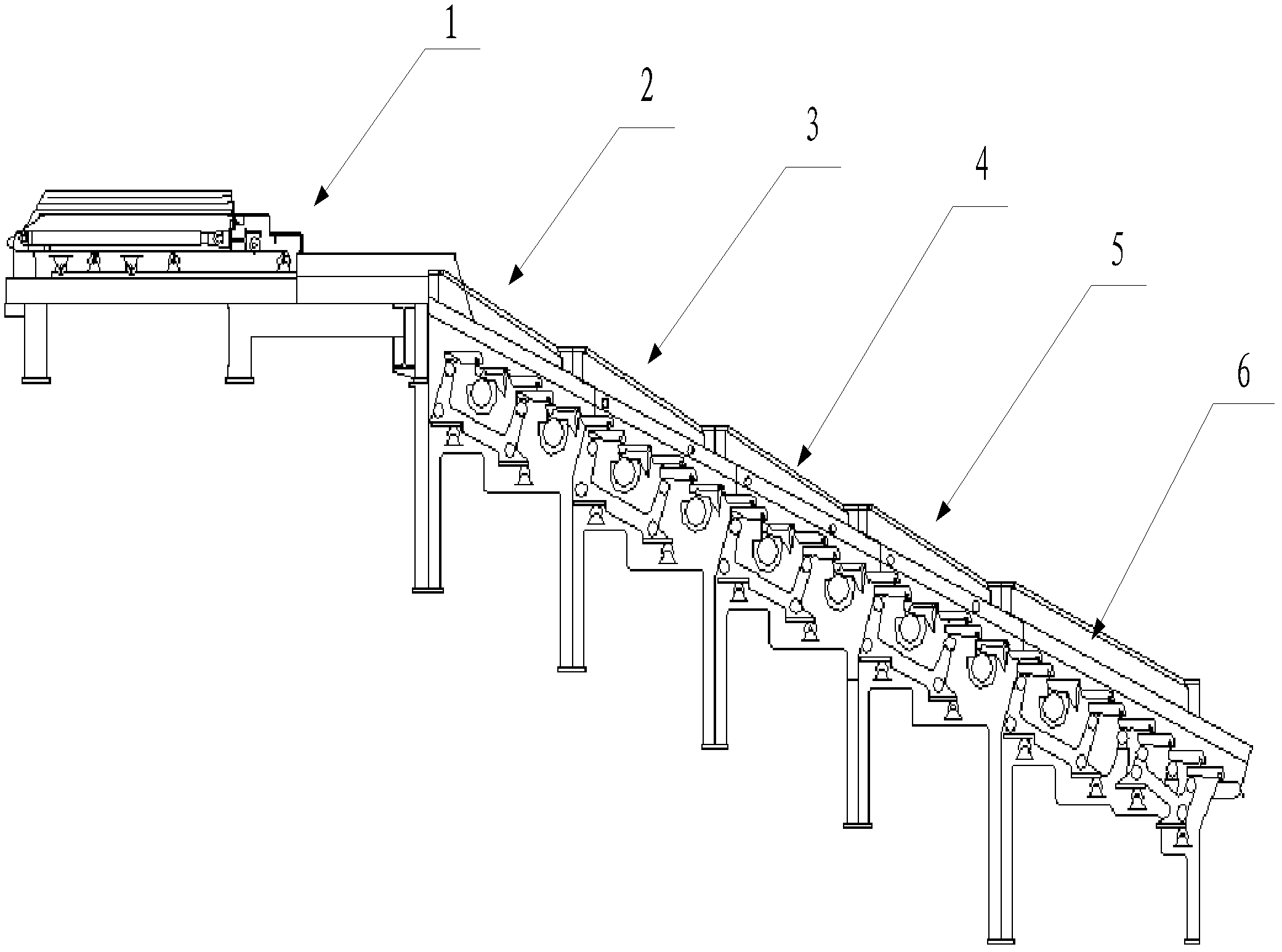
The invention provides a multistage hydraulic mechanical garbage incinerator, which comprises a feeding port, a feeding fire grate, an incinerating fire grate, a primary air supply system and a secondary air supply system. The incinerating fire grate is longitudinally divided into five units, wherein the first unit, the second unit, the third unit and the fourth unit are standard units, the fifth unit is a tail end lengthened unit, each unit comprises a plurality of sliding fire grate segments, turning fire grate segments and fixed fire grate segments, and the incinerating fire grate is integrally divided into a drying section, a burning section and a burnout section by the five units along the garbage moving direction. The multistage hydraulic mechanical garbage incinerator is characterized in that a limiting support device for limiting a feeding trolley to move upward is arranged on the upper surface of a tail of the feeding trolley of the feeding fire grate. By the aid of the multistage hydraulic mechanical garbage incinerator, the shortcomings of an existing garbage incinerator are improved, and burnout ratio of garbage incineration is increased.

Description

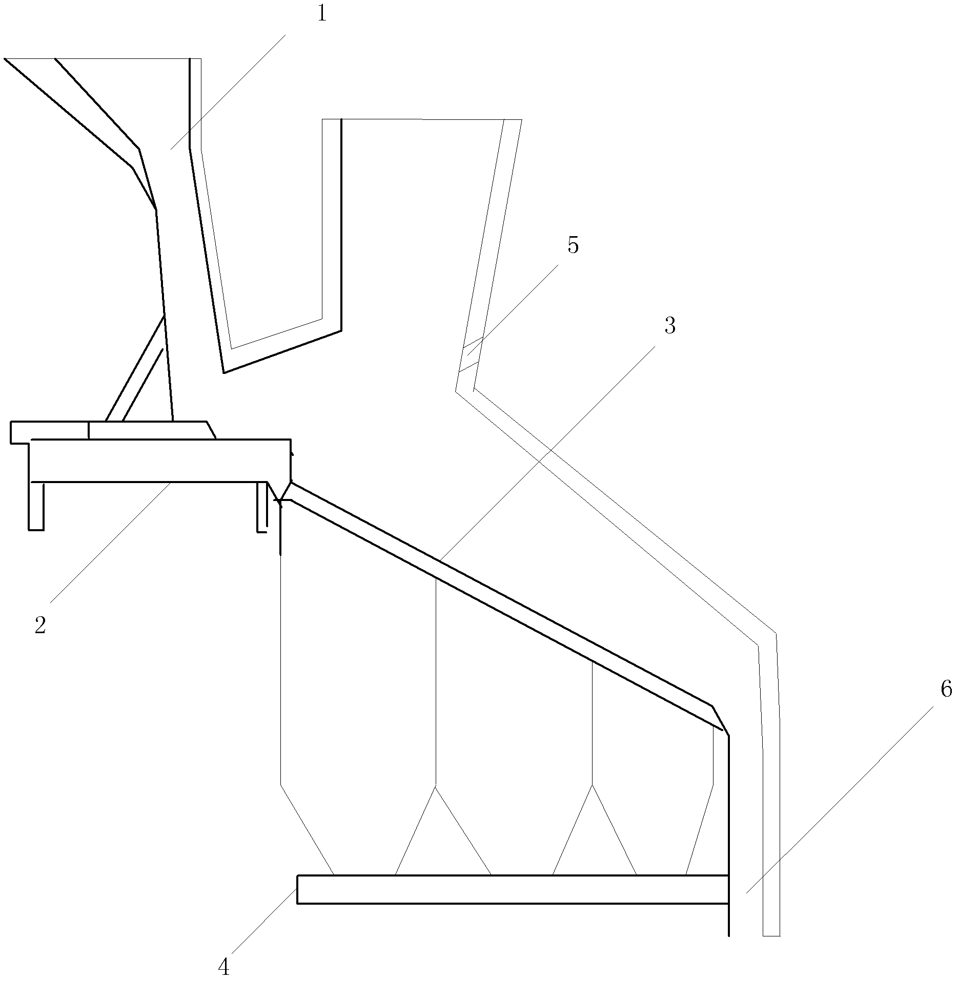
technical field [0001] The invention relates to the incineration of garbage and other wastes, in particular to a multi-stage hydraulic mechanical garbage incinerator. Background technique [0002] Waste incineration is one of the main ways to realize waste reduction, harmless and resourceful treatment. At present, garbage incineration has gradually become the main way to deal with urban domestic garbage. After modern incineration, the volume of garbage can generally be reduced by 80%-90%. At the same time, various pathogens can be eliminated, and harmful substances can be converted into harmless substances. resource utilization. [0003] Existing waste incineration mostly adopts a mechanical waste incinerator with an incineration grate, and the grate mainly includes: a forward push reciprocating fire grate, a reverse push reciprocating fire grate, a drum type fire grate, and the like. figure 1 The shown garbage incinerator is just a kind of garbage incinerator that adopts ...

Claims


Application Information

Patent Timeline
Patent Type & Authority Applications(China)
IPC IPC(8): F23G5/04F23G5/44
CPCF23G5/002F23H17/12F23G5/05F23H7/08F23G2207/30F23H17/08F23G2205/101F23G5/444F23H3/02F23G5/50
Inventor 陈涛韩乃卿朱福刚张洪波温俊明张宾邵哲如
Owner EVERBRIGHT ENVIRONMENTAL PROTECTION TECHCAL DEV BEIJING
Why Eureka
Try Eureka