Fluid admission system for providing a pressure-balanced valve

a technology of fluid admission system and valve body, which is applied in the direction of diaphragm valve, pressure relieving device on sealing face, application, etc., can solve the problems of electrically actuated valves typically not being used with large engines, high pressure and flow rate of fuel admission systems used with large internal combustion engines, and high flow rate of fluid admission systems. , to achieve the effect of eliminating valve lock-up

Active Publication Date: 2012-09-25
WOODWARD GOVERNOR CO
View PDF13 Cites 28 Cited by
  • Summary
  • Abstract
  • Description
  • Claims
  • Application Information

AI Technical Summary

Benefits of technology

[0009]The present invention has numerous features that can be used together or in combination. The present invention relates to new and improved fluid admission systems that provide for use of electronic actuators to drive a valve. More particularly, the present invention relates to new and improved fluid admission systems that include balanced or partially balanced valves. One benefit of embodiments of the present invention is that the pressure related forces acting on opposite sides of the movable portions of the valve are substantially more equal, reducing the forces needed to drive the movable portions of the valve to an open condition. A further benefit of one or more embodiments of the present invention is that the balancing of the valve substantially eliminates valve lock-up due to rapid throttling down of the engine in prior art fluid admission systems.
[0013]In a preferred embodiment, the first balancing area and the first effective area are equal and the second balancing area and the second effective area are equal. This will render the fluid admission system, and particularly the movable metering plate, balanced such that pressure differentials will not significantly effect the actuation force required to transition to the open position.

Problems solved by technology

In fluid flow designs for high pressure industrial applications, for example, high pressure fluid flow through a valve may create forces which tend to close the valve, particularly when the valve is in or near a fully closed position.
Fuel admission systems for use with large internal combustion engines in industrial or mobile applications may involve significantly high pressures and flow rates.
Due to force limitations, electrically actuated valves generally produce lower actuation forces than that achieved with mechanical and / or hydraulic actuators.
As a result, electrically actuated valves have typically not been used with large engines in industrial or mobile applications requiring high actuation forces.
In addition to the force limitation issues associated with electrically actuated valves, a problem in the operation of these valves can result when an engine operator or engine system rapidly rejects load.
Such rapid throttle closure results in a dramatic drop in intake manifold pressure, reducing the pressure on the downstream side of the valves below their normal operating pressure.
However, as the upstream side of the valves are still exposed to high pressure fluid (fuel), the pressure differential across the movable metering plates and movable portions of the valves increases.
Unfortunately, this spike in pressure differential due to the drop in intake manifold pressure at the (fuel admission valve outlet) can lock the valves in their closed position and prevent them from being opened via their actuation systems.
Such locking of the fuel admission valves will then stall engine operation until normal valve function is restored.
Further amplifying this problem is the lack of a simple way to release the pressure on the high pressure side of the valve to unlock the valve.
While there have been attempts to add supplemental pressure relief arrangements to address this valve lock-up problem, this adds complexity and expense to the fuel admission system.
Further, many of these fuel admission systems are restricted in size.
In such applications, the pressure relief arrangements designed to address this problem cannot be installed due to insufficient space.

Method used


Image

  • Fluid admission system for providing a pressure-balanced valve
  • Fluid admission system for providing a pressure-balanced valve
  • Fluid admission system for providing a pressure-balanced valve

Examples


Embodiment Construction

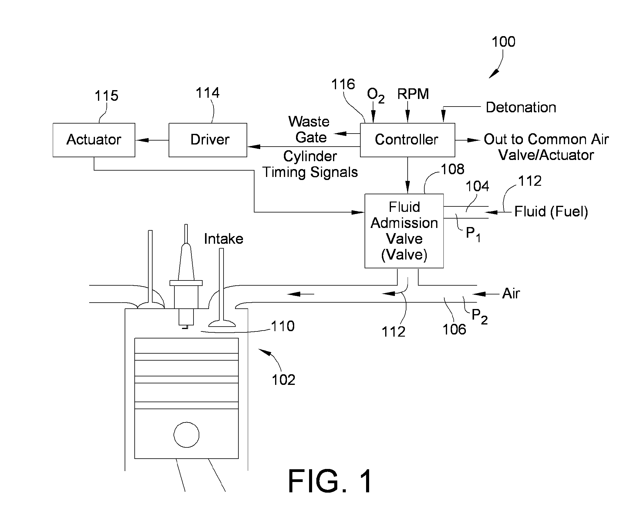
[0035]Referring to FIG. 1, an embodiment of a fluid admission system 100 for use with an internal combustion engine 102 is shown. The engine 102 may be a multiple cylinder, large bore engine capable of generating extremely high power for use in industrial applications. Although the fluid admission system 100 is shown associated with an internal combustion engine 102 in FIG. 1, it is to be understood that the fluid admission system 100 is not specific to a particular type of engine configuration or application. For example, the fluid admission system 100 may be used with a reciprocating air and gas compressor, a continuous combustion engine (e.g., a turbine engine), a compression ignition engine, and the like.

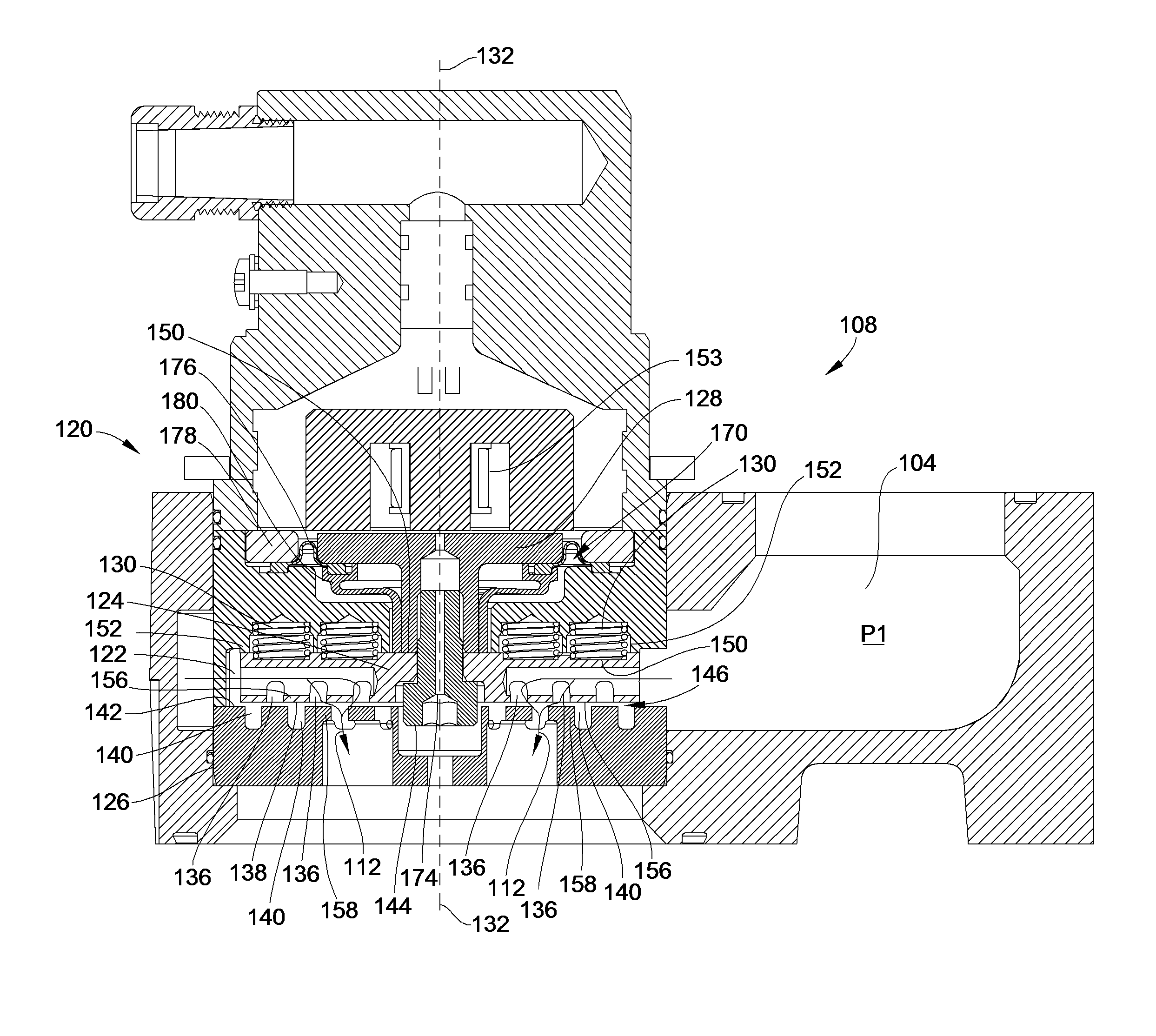
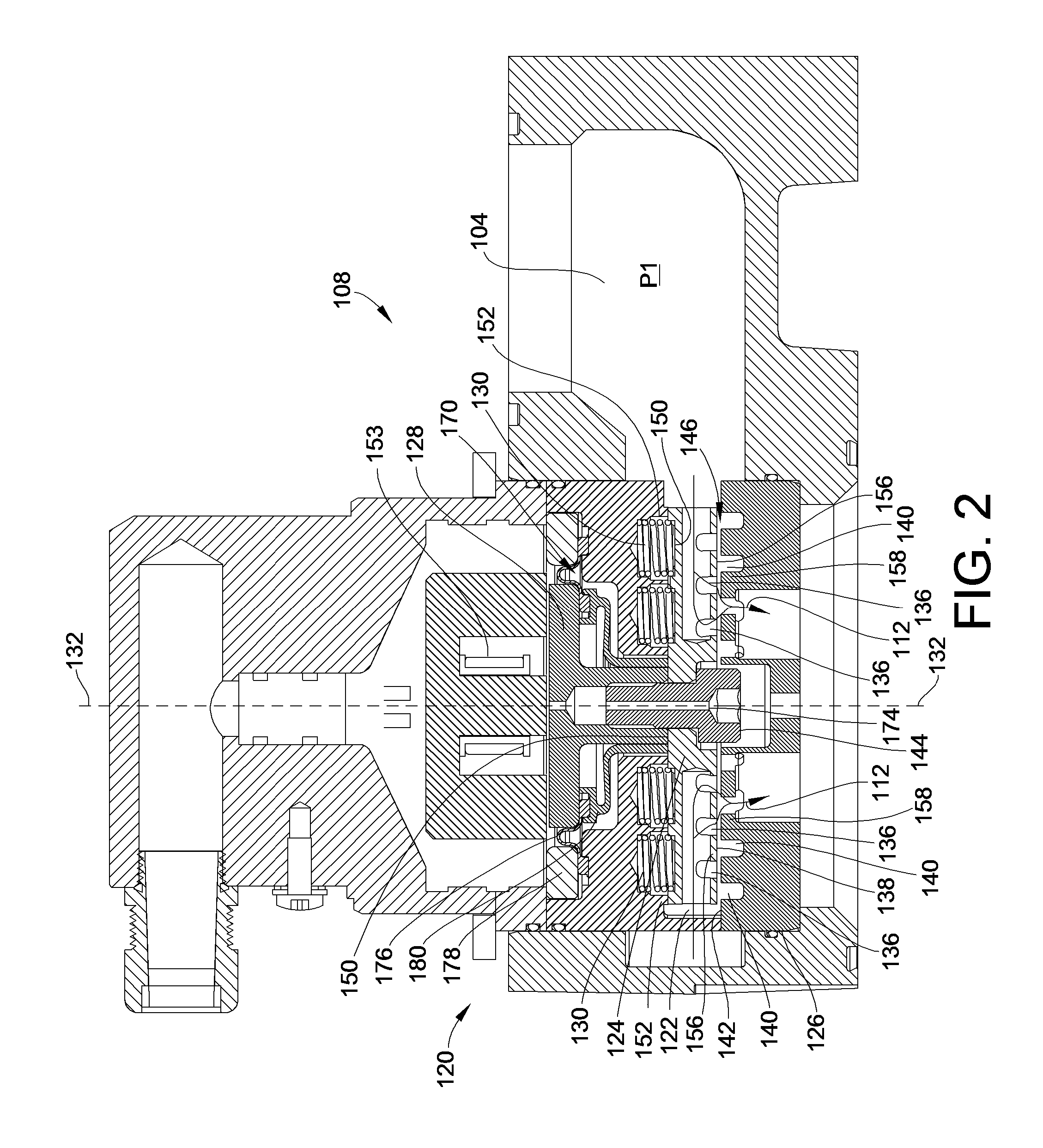
[0036]As illustrated, the fluid admission system 100 includes a fluid supply manifold 104, an air intake manifold 106, a fluid admission valve 108 located between the fluid supply manifold 104 and the air intake manifold 106, and a combustion cylinder 110. When the fluid admissi...


PUM


Abstract

A valve assembly includes a valve housing located between a fluid inlet region maintained at a first pressure and a fluid outlet region maintained at a second pressure. A movable metering plate is located within valve housing. A fixed metering plate interacts with the movable metering plate to meter fluid flow through the valve housing. An armature is coupled to the movable metering plate and is configured to move the movable metering plate from a closed position toward an open position. The fluid admission system further includes a balancing region to balance pressure related forces acting on the movable portions of the valve, including the metering plate. A balance passageway is in communication with the balancing region and the fluid outlet region to maintain the balancing region at the second pressure of the fluid outlet region when the movable metering plate is in the closed position.

Description

CROSS-REFERENCE TO RELATED PATENT APPLICATIONS[0001]This patent application claims the benefit of U.S. Provisional Patent Application No. 61 / 061,327, filed Jun. 13, 2008, the disclosure and teachings of which are incorporated herein, in their entireties, by reference.TECHNICAL FIELD[0002]This invention generally relates to a fluid admission system and, more particularly, to a fluid admission system for balancing pressure related forces across a valve.BACKGROUND[0003]In fluid flow designs for high pressure industrial applications, for example, high pressure fluid flow through a valve may create forces which tend to close the valve, particularly when the valve is in or near a fully closed position. This flow force increases the actuation force required to stroke or open the valve. Fuel admission systems for use with large internal combustion engines in industrial or mobile applications may involve significantly high pressures and flow rates. Generally, mechanically and / or hydraulicall...

Claims


Application Information

Patent Timeline
Patent Type & Authority Patents(United States)
IPC IPC(8): F16K31/00
CPCF02M51/0642F16K31/0689F02M21/0239Y02T10/32Y02T10/30Y10T137/86718Y10T137/87418
Inventor FARROW, TIMOTHY J.BRODSACK, GREGORY J.WITT, RONALD L.
Owner WOODWARD GOVERNOR CO
Why Eureka
Try Eureka