

Bone removal tool
a bone and tool technology, applied in the field of bone removal tools, can solve the problems of pain and disability, decreased space between the vertebrae, persistent pain, etc., and achieve the effect of efficient and precise preparation of the bone surfa
- Summary
- Abstract
- Description
- Claims
- Application Information
AI Technical Summary
Benefits of technology
Problems solved by technology
Method used
Image

Examples
Embodiment Construction
[0029]The present invention provides an instrument for removing bone and cartilage or other tissue to prepare the bone surface for receiving an implant. The present invention will be described below relative to an illustrative embodiment. Those skilled in the art will appreciate that the present invention may be implemented in a number of different applications and embodiments and is not specifically limited in its application to the particular embodiments depicted herein.
[0030]The bone removal instrument of an illustrative embodiment of the invention may be used in spinal surgery, for example, during a spinal fusion or disc replacement procedure to prepare the vertebral endplates for placement of the implant, though one skilled in the art will recognize that the invention can be used with any implant in any surgical procedure that requires preparation of a bone surface.
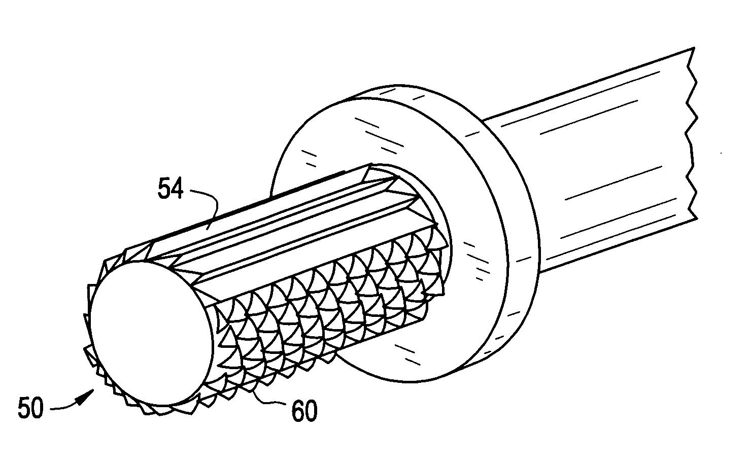
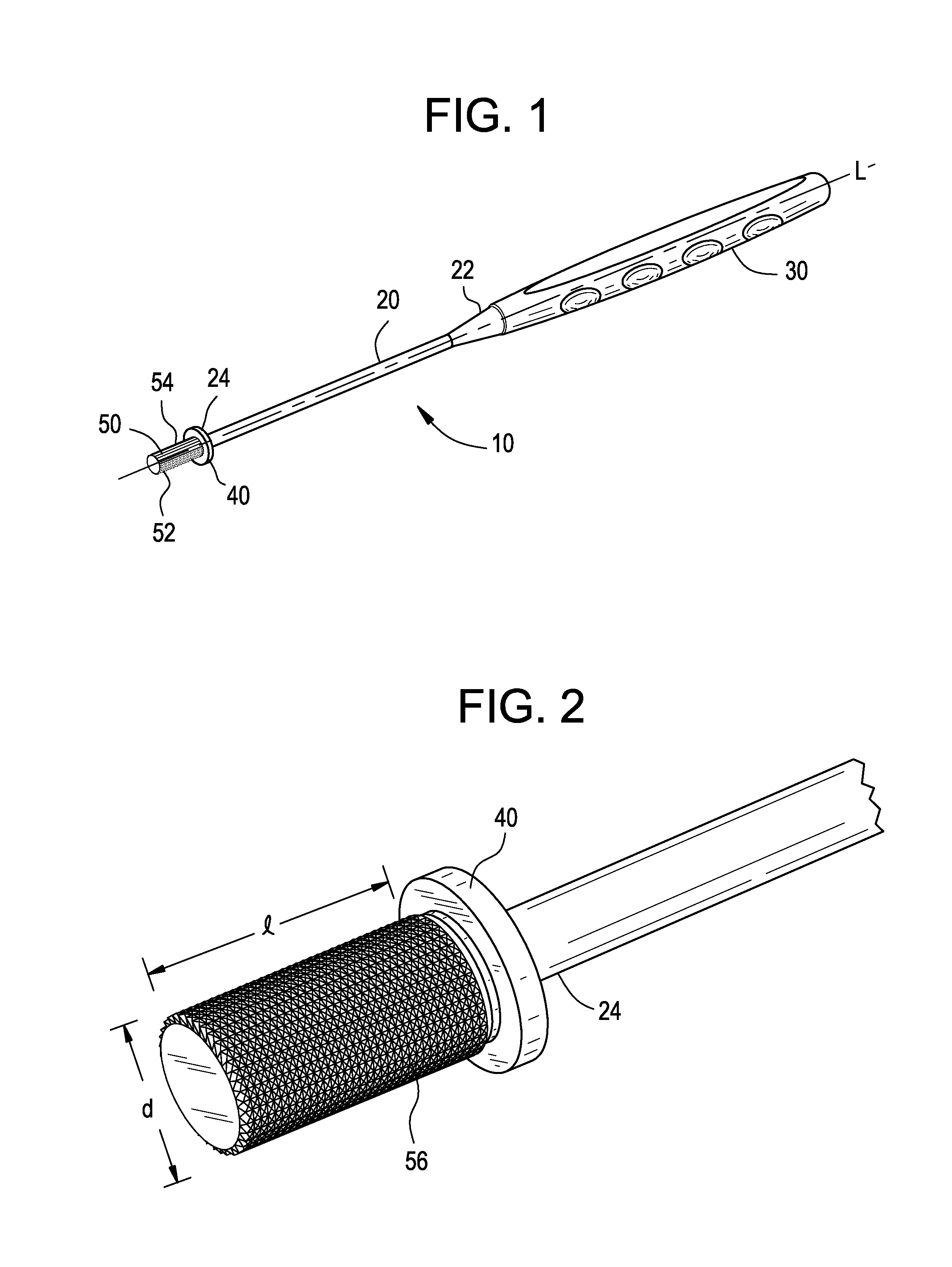
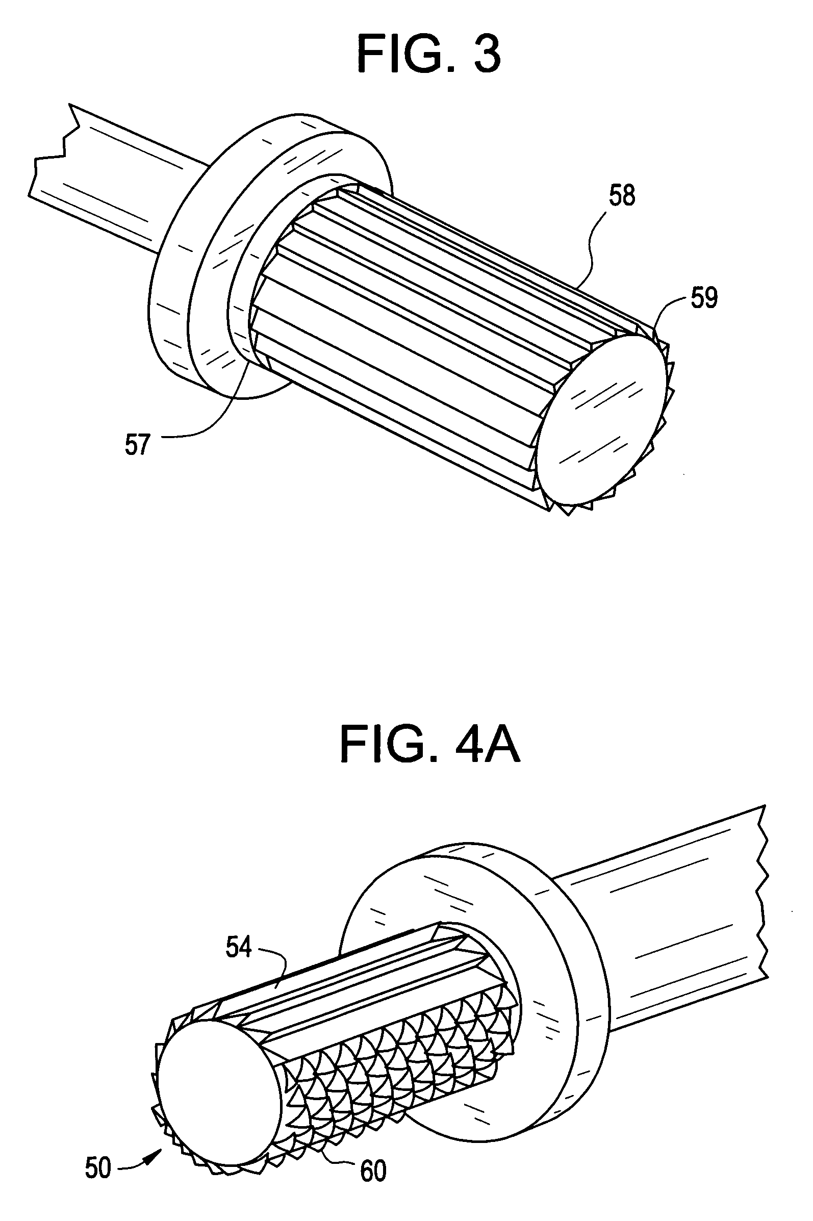
[0031]Referring to FIG. 1, a bone removal instrument 10 is shown that prepares the bone surface for receiving an i...
PUM
 Abstract
Description
Claims
Application Information