
Core-based satellite network architecture

a satellite network and core technology, applied in the field of satellite networks, can solve the problems of low service and functionality of satellite network implementations, high cost of building and maintaining gateways, and failure to provide satellite network services and functionality at layer-2 (i.e., layer 2)

Active Publication Date: 2012-10-02
VIASAT INC
View PDF47 Cites 15 Cited by
  • Summary
  • Abstract
  • Description
  • Claims
  • Application Information

AI Technical Summary

Benefits of technology

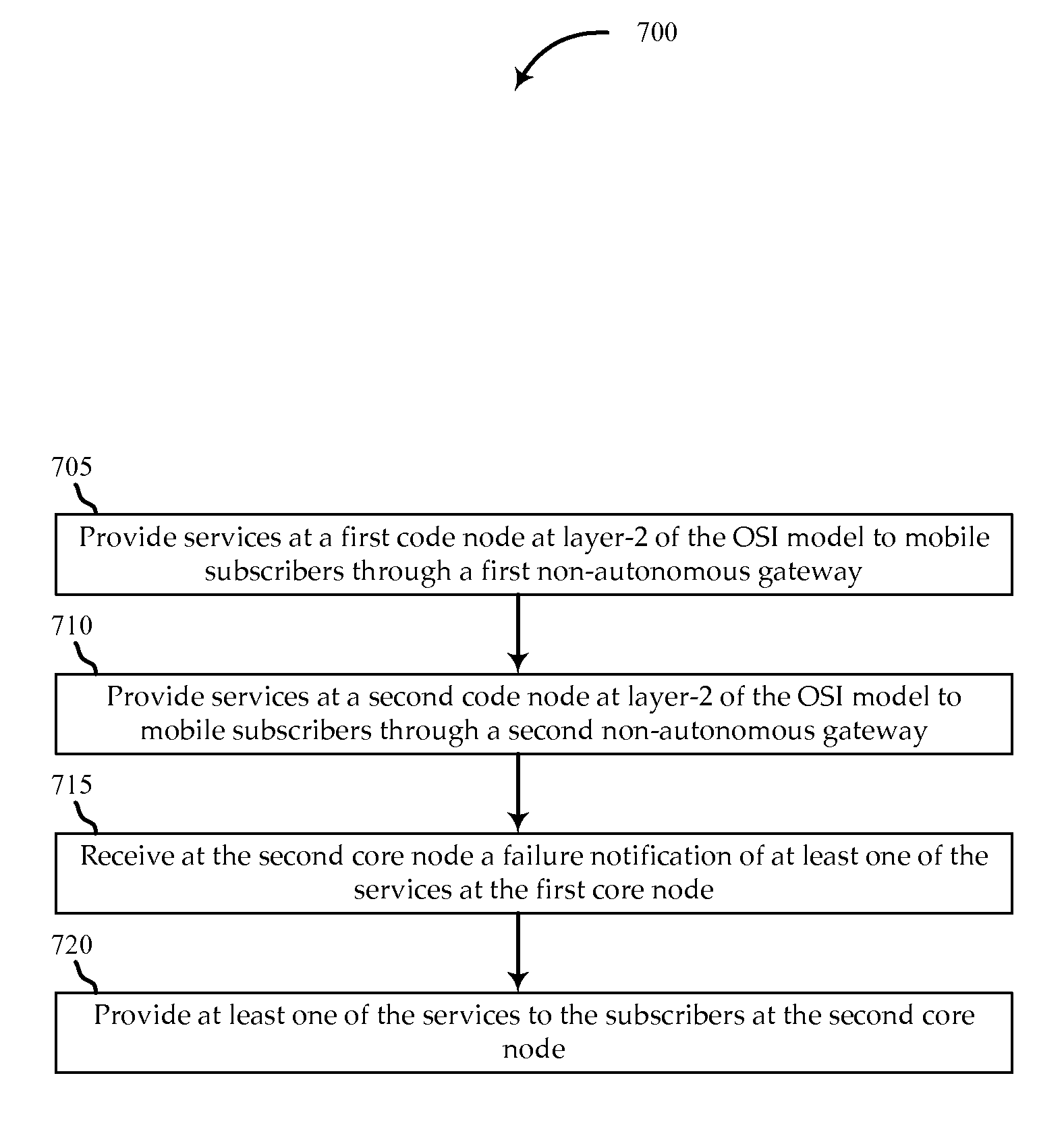
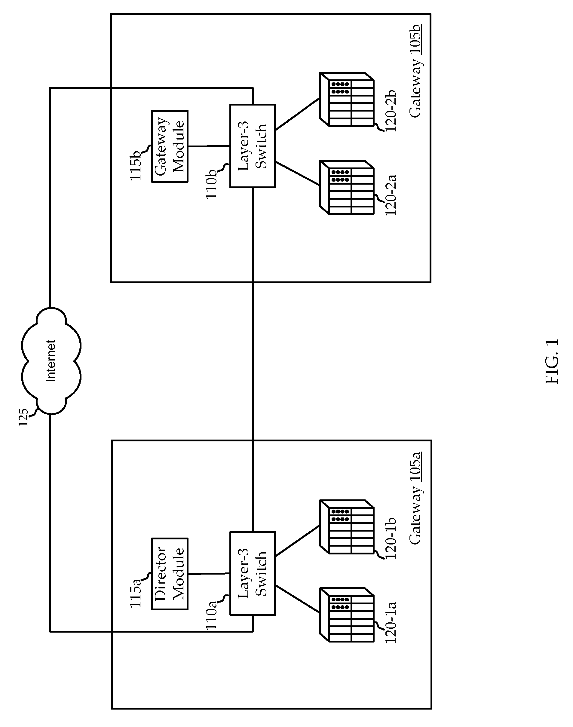
The patent describes a system that provides redundant core nodes in a network, which can communicate with satellite gateways and offer networking services to subscribers. In case of failure, a second core node can take over the duties of the first one and provide the same services to the subscribers. This ensures that the network remains operational even in the event of a failure.

Problems solved by technology

Such gateways are expensive to build and maintain.
Furthermore, the services and functionality offered by these gateways are isolated to the customers for which the gateway specifically service.
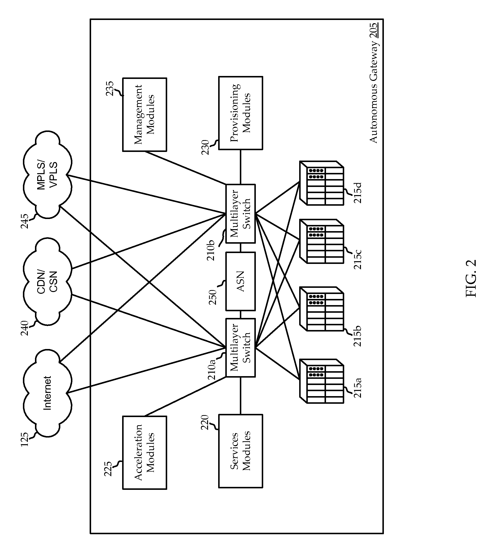
Further, current implementations of satellite networks fail to provide the services and functionality at layer-2 (i.e., layer-2 of the ISO-model stack) communicating from one point on the network to another.
Additionally, current implementations of satellite networks only provide redundancy within the gateway.
For example, current satellite network implementations may provide redundant access to a points on the network (i.e., multiple fiber lines to a gateway such that if one line is compromised, service still continues over the second line); however, if, for example, the gateway itself is down (or a service of the gateway), there is currently no way for another gateway to continue to provide the service (or services) of a failed gateway.
Accordingly, such a deployment includes a layer-3 network over an MPLS underlying network, so each core node or gateway is routed (i.e., the MAC header of packets transmitted are altered), thus limiting the capabilities of the network.

Method used


Image

  • Core-based satellite network architecture
  • Core-based satellite network architecture
  • Core-based satellite network architecture

Examples


Embodiment Construction

[0018]The ensuing description provides exemplary embodiment(s) only, and is not intended to limit the scope, applicability or configuration of the disclosure. Rather, the ensuing description of the exemplary embodiment(s) will provide those skilled in the art with an enabling description for implementing an exemplary embodiment, it being understood that various changes may be made in the function and arrangement of elements without departing from the spirit and scope as set forth in the appended claims. Some of the various exemplary embodiments may be summarized as follows.

[0019]Aspects of the invention include implementing nodes which provide intelligence and functionality (e.g., services, etc). Furthermore, the nodes are interconnected with gateways which provide connectivity to satellites. As such, enterprises, content distribution networks (CDNs), etc. are able to connect to any node or other point in the network (including gateways), and seems like being plugged in to any other...


PUM


Abstract

Systems and methods for implementing a satellite network, are described. The system includes satellite gateways in communication with subscribers over a satellite communication network. The satellite gateways send network communications to the subscribers and receive network communications from the subscribers. The system further includes a first core node in communication with at least one of the satellite gateways. The first core node provides networking services, at L2, to a first subset of subscribers. The system further includes a second core node in communication, at L2, with one of the satellite gateways and the first core node. The second core node provides the networking services, at layer-2 of the OSI model, to a second subset of the subscribers. In response to failure of at least one of the networking services in the first core node, the second core node providing the at least one of the services to the first subset of the subscribers.

Description

PRIORITY CLAIM[0001]This application claims priority to U.S. Provisional Application No. 61 / 170,359, entitled DISTRIBUTED BASE STATION SATELLITE TOPOLOGY, filed on Apr. 17, 2009, and also claims priority to U.S. Provisional Application No. 61 / 313,017, entitled CORE-BASED SATELLITE NETWORK ARCHITECTURE, filed on Mar. 11, 2010, which are both incorporated by reference in their entirety for any and all purposes.RELATED APPLICATIONS[0002]This application is related to U.S. Provisional Application No. 61 / 254,551, entitled “Layer-2 Connectivity From Switch to Access Node / Gateway”, filed on Oct. 23, 2009, U.S. Provisional Application No. 61 / 254,553, entitled “Access Node / Gateway to Access Node / Gateway Layer-2 Connectivity (End-to-End)”, filed on Oct. 23, 2009, and U.S. Provisional Application No. 61 / 254,554, entitled “Layer-2 Extension Services”, filed on Oct. 23, 2009, which are all incorporated by reference herewith in their entirety for any and all purposes. The application is also rela...

Claims


Application Information

Patent Timeline
Patent Type & Authority Patents(United States)
IPC IPC(8): G01R31/08
CPCH04B7/18584H04B7/18591H04L12/462H04L43/0811H04L41/06H04L41/5054H04L41/344
Inventor FOXWORTHY, MICHAELCHANDRAN, GIRISHLAU, JASON
Owner VIASAT INC
Learn More