
Positioning of teat cups

a technology for teat cups and teat cups, applied in milking devices, catheters, dairy products, etc., to achieve the effect of reliable, flexible and efficient solution

Inactive Publication Date: 2012-10-09
DELAVAL HLDG AB
View PDF13 Cites 6 Cited by
  • Summary
  • Abstract
  • Description
  • Claims
  • Application Information

AI Technical Summary

Benefits of technology

The present invention provides an efficient, reliable, and flexible solution for fetching teat cups in a teat cup magazine where the position of the magazine and the robotic arm is variable. This is achieved by using a reference entity that has a fixed spatial relationship to the teat cup magazine and allows the remote detecting means to receive wireless energy reflected against the reference entity while moving the robotic arm towards the at least one teat cup for removal. The reference entity can be a separate entity or a part of the at least one teat cup. The invention offers a cost-efficient and flexible solution for fetching teat cups and is particularly useful in challenging environments.

Problems solved by technology

Nevertheless, due to the multitude of moving parts, this is associated with particular problems.
Namely here, the position of the teat cup magazine and the teat cups stored therein varies over time, and therefore it is a challenging task to control a milking robot arm to withdraw the teat cups from the teat cup magazine.

Method used


Image

  • Positioning of teat cups
  • Positioning of teat cups
  • Positioning of teat cups

Examples


first embodiment

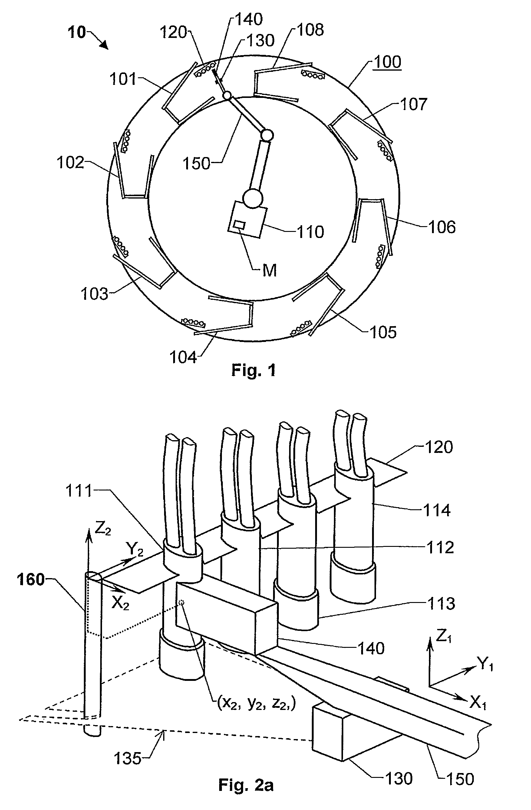
[0028]Turning now again to FIG. 2a, we see a block diagram over the proposed arrangement for fetching teat cups. Here, teat cups 111, 112, 113 and 114 are located in the teat cup magazine 120.

[0029]The robotic arm 150 carries the gripper means 140, which in turn, is configured to hold at least one teat cup 111 during removal of this teat cup from the teat cup magazine 120. The position for the robotic arm 150 is defined in a primary reference system X1, Y1, Z1, whereas the respective positions for the teat cups 111, 112, 113 and 114 are defined in a secondary reference system X2, Y2, Z2. Hence, for example the position for the teat cup 111 in the secondary reference system X2, Y2, Z2 are given by a set of coordinates x2, y2, z2. Analogously, the positions for the remaining teat cups 112, 113 and 114 in the teat cup magazine 120 are given by a respective set of coordinates in the secondary reference system X2, Y2, Z2. As mentioned above, the relationship between the first and seconda...

second embodiment

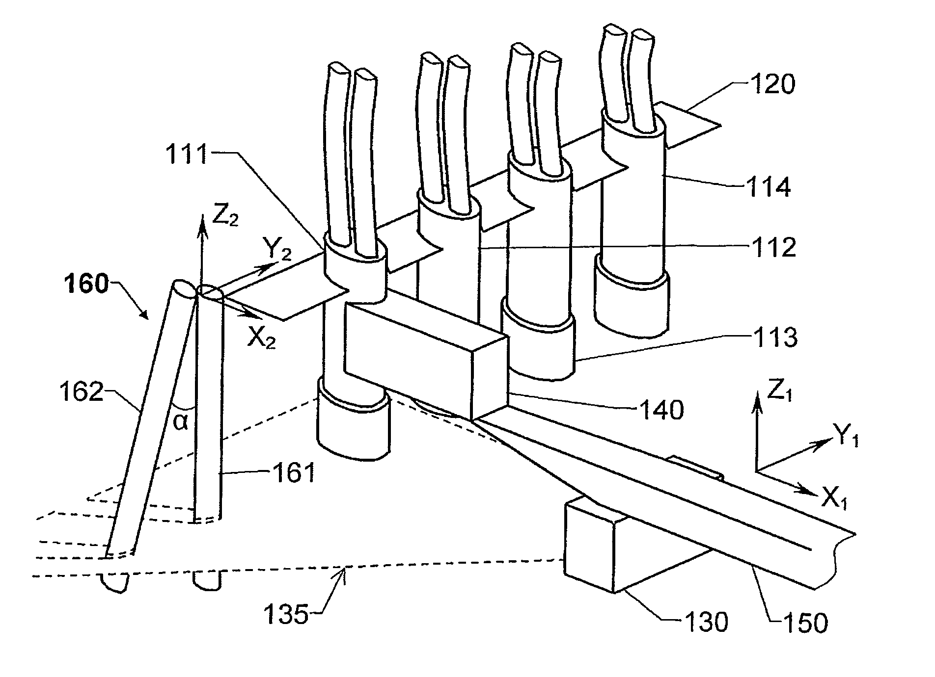
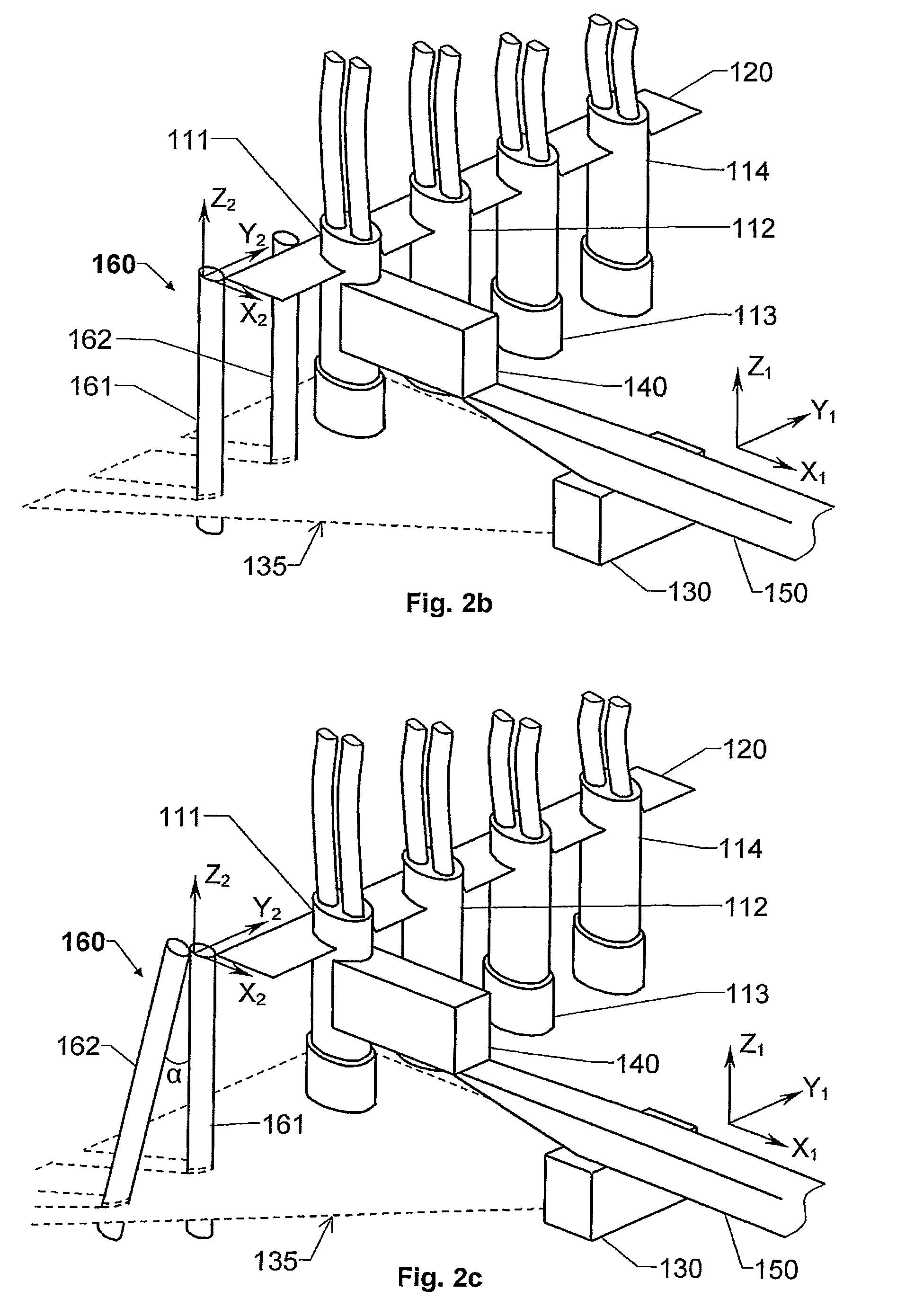
[0042]Moreover, in the invention, the second rod member 162 is preferably oriented such that a symmetry axis thereof is essentially parallel with the symmetry axis of the first rod member 161. For example, the rod members 161 and 162 may be parallel with the symmetry axes of the teat cups 111, 112, 113 and 114 in the teat cup magazine 120 as illustrated in FIG. 3. One effect of this configuration is that, depending on a rotation angle φ of the teat cup magazine 120 and its teat cups 111, 112, 113 and 114 in the X1Y1-plane of the primary reference system, a distance d1 between a coordinate x and x′ respectively for the rod members 161 and 162 registered by the remote detection means 130 from its position (e.g. on the robotic arm 150) varies. In the example illustrated in FIG. 3, a relatively small rotation angle φ (−90°≦φ≦90°) corresponds to a comparatively large distance d1; and vice versa, a relatively large rotation angle φ corresponds to a comparatively small distance d1.

[0043]Th...


PUM


Abstract

An arrangement for fetching a teat cup from a teat cup magazine in which each teat cup has a respective fixed position includes a reference entity in a fixed spatial relationship to the teat cup magazine and each teat cup stored therein; a remote detecting element that registers wireless energy reflected by the reference entity, and based thereon determines a respective position for the teat cup relative to a robotic arm. The robotic arm carries a gripper element configured to hold the teat cup during removal thereof from the teat cup magazine. The reference entity is configured to allow the remote detecting element to receive wireless energy reflected against the reference entity while moving the robotic arm towards the least one teat cup for removing the at least teat cup from the teat cup magazine.

Description

THE BACKGROUND OF THE INVENTION AND PRIOR ART[0001]The present invention relates generally to automatic milking of animals. More particularly the invention relates to an arrangement for fetching teat cups according to the preamble of claim 1 and a milking installation according to claim 13. Moreover, the invention relates to a method according to the preamble of claim 14, a computer program according to claim 24 and a computer readable medium according to claim 25.[0002]The technical solutions for automatic milk extraction are becoming increasingly efficient and sophisticated. For example, today's milking robots allow a completely automatic milking procedure. In movable milking parlors, however, a human operator normally needs to be involved in at least some steps of the milking procedure. Of course, for enhanced efficiency it is desirable to minimize the involvement of a human operator. Therefore, it would be advantageous if one or more milking robots could be engaged in a milking-...

Claims


Application Information

Patent Timeline
Patent Type & Authority Patents(United States)
IPC IPC(8): A01J5/007
CPCA01J5/0175
Inventor NILSSONHALLSTROM, ANDERS
Owner DELAVAL HLDG AB
Learn More