Independent cleaning of interfaces between separable fluid systems

a technology of separable fluid and interface cleaning, which is applied in the direction of cleaning using liquids, cleaning processes and apparatuses, and cleaning using liquids. it can solve the problems of inability to mix the milk of healthy animals' milk with the milk and the manual cleaning of the milking robot out of operation is highly inefficient. it is reliable and flexible, and the effect of efficient cleaning

Active Publication Date: 2015-07-07
DELAVAL HLDG AB
View PDF15 Cites 6 Cited by
  • Summary
  • Abstract
  • Description
  • Claims
  • Application Information

AI Technical Summary

Benefits of technology

[0005]The object of the present invention is therefore to solve the above problem and thus offer an efficient, reliable and flexible solution for cleaning the interfaces between any separable fluid systems of a milking installation. According to one aspect of the invention, the object is achieved by the initially described milking installation, wherein the first fluid system includes a by-pass arrangement configured to allow fluid in the first fluid system to circulate independently from the passage of fluid through the common cavity when the common cavity is included in the second fluid system
[0006]This design is advantageous because it enables efficient cleaning of all pipes, cavities and valves of the milking installation including the valve surfaces of the interfaces between the separable fluid systems. Furthermore, the by-pass arrangement renders it possible to operate the first and second fluid systems independently from one another, such that for example the first fluid system is cleaned while milk is being emptied from the second fluid system.
[0007]According to a preferred embodiment of this aspect of the invention, the first fluid system includes a drain outlet configured to enable output of fluid from the first fluid system. Preferably, this drain outlet is used in connection with replacing fluids in the first fluid system, e.g. when introducing a first cleaning fluid after milking, or when introducing a second cleaning fluid after a first ditto. Hence, the procedure may involve the consecutive steps of: opening the drain outlet, discharging an existing fluid in the first fluid system via the drain outlet, closing the drain outlet, and passing cleaning fluid through the first fluid system. Thereby, the risk for undesired mixing of different fluids in the first fluid system can be made very small.
[0008]According to another preferred embodiment of this aspect of the invention, at least one valve interface of the common cavity's valve interfaces is associated with a shut-off arrangement, which when said valve interface is in a closed state is configured to trap a working fluid in a barrier cavity adjoining said valve interface. The trapped working fluid has a pressure level exceeding both a first pressure level in the first fluid system and a second pressure level in the second fluid system. Consequently, when the shut-off arrangement is closed, the risk of leakage between the first and second fluid systems is eliminated.
[0009]According to yet another preferred embodiment of this aspect of the invention, the installation includes at least one milk extraction station and a milk tank. Each milk extraction station is here configured to automatically withdraw milk from at least one animal, and each milk extraction station is included in the first fluid system. The milk tank is configured to receive extracted milk from the at least one milk extraction station. The milk tank is further included in the second fluid system. Hence, the milk extraction stations and the milk tank may be efficiently separated from one another. It is also rendered possible to clean all sealing surfaces between these fluid systems in a reliable and straightforward manner.
[0010]According to a further preferred embodiment of this aspect of the invention, each sealing surface of the common cavity's valve interfaces is accessible for through passage of fluid via at least one of the first and second fluid systems while the first and second fluid systems are disconnected from one another. This is advantageous because thereby the common cavity and its valve interfaces may be cleaned adequately in a straightforward manner.

Problems solved by technology

Moreover, taking the milking robot out of operation to manually clean its milk line system is a highly inefficient strategy.
Namely, one or more animals using the milking robot may undergo medical treatment, and therefore their milk cannot be mixed with the milk from the healthy animals.

Method used


Image

  • Independent cleaning of interfaces between separable fluid systems
  • Independent cleaning of interfaces between separable fluid systems
  • Independent cleaning of interfaces between separable fluid systems

Examples


first embodiment

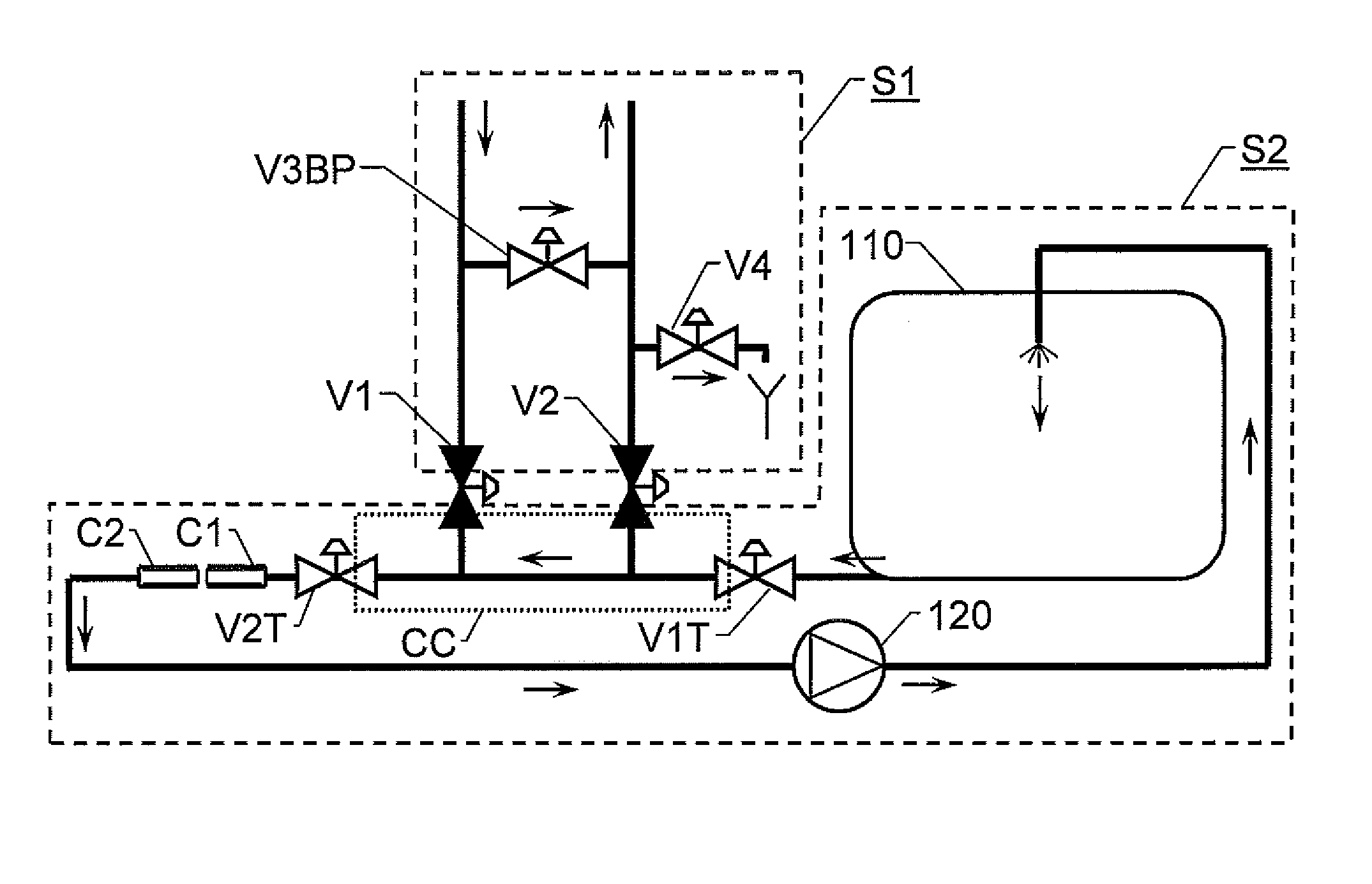
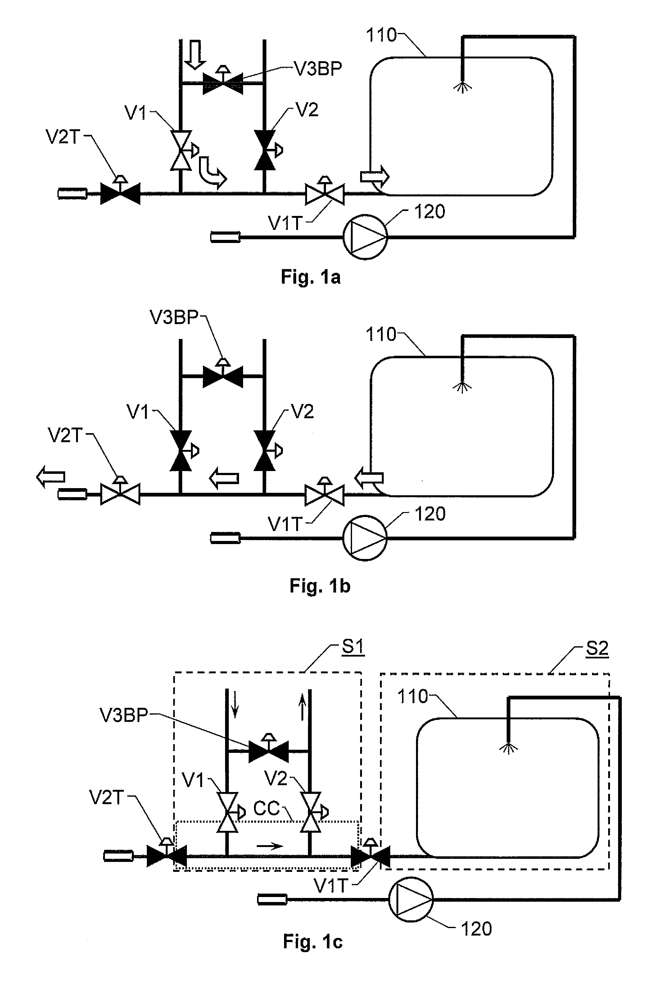
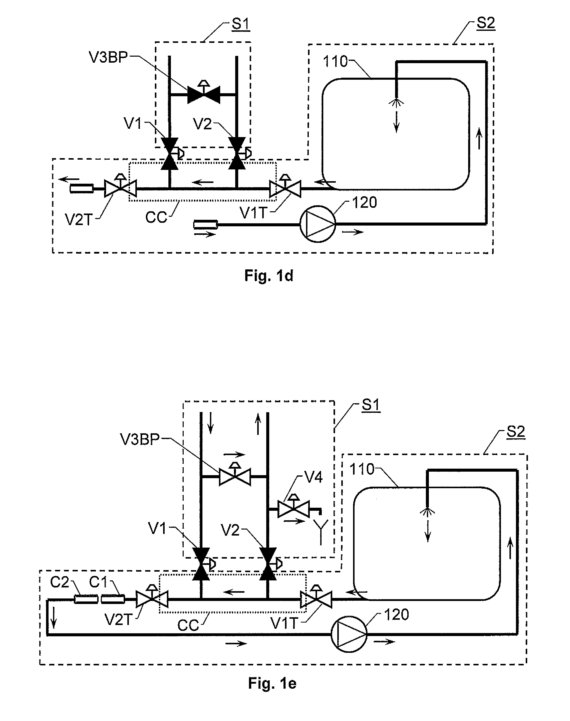
[0024]FIG. 1a shows a schematic view over an interface between a milk extraction station (not shown) and a milk tank 110 according to the invention. Here, the milk extraction station withdraws milk from an animal and via a milk line system forwards the milk into the milk tank 110. To this aim, a first milk line valve means V1 and a first tank valve means V1T are open. To avoid recirculation of the milk into the milk line system, a second milk line valve means V2 is closed. A valve means V3BP of a by-pass arrangement is likewise closed. Further, a second tank valve means V2T towards an external connection is also closed, such that the milk is forced into the milk tank 110.

[0025]FIG. 1b shows the interface of FIG. 1a during emptying of the milk tank 110. Now, the first and second milk line valve means V1 and V2 respectively are closed, and both the first and second tank valve means V1T and V2T are open. Consequently, the milk from the tank 110 exits through the external connection wit...

second embodiment

[0035]FIG. 2a shows a schematic view over an interface between a milk extraction station and a milk tank 110 according to the invention. Here, tank valve means V1T and V3T respectively and milk line valve means V1 and V3 have interfaces towards the common cavity CC. Another tank valve means V2T is also included to provide external access to the milk tank 110.

[0036]FIG. 2a illustrates a situation when the first and second fluid systems S1 and S2 are not in fluid communication with one another, and fluid is passed through the first fluid system S1 (e.g. for cleaning purposes). To this aim, the tank valve means V1T and V3T are closed and the milk line valve means V1 and V3 are open. Consequently, the sealing surfaces of the latter valve means of the common cavity CC is accessible for through passage of fluid in the first fluid system S1. At the same time, milk can be taken out from the milk tank 110 via the tank valve means V2T.

[0037]To ensure proper cleaning of the by-pass arrangement...

third embodiment

[0040]FIG. 3a shows a schematic view over an interface between a milk extraction station and a milk tank 110 according to the invention in a situation analogous to that illustrated in FIG. 2a (i.e. when fluid is passed through the first fluid system S1). In addition to the components and units described above with reference to FIGS. 2a and 2b, the embodiment shown in FIG. 3a includes a respective shut-off arrangement associated with the valve interfaces V12, V12T and V3T towards the common cavity CC. When either of these valve interfaces is in a closed state, the shut-off arrangement is configured to trap a working fluid in a barrier cavity VB1, VB2 and VB3 respectively. The barrier cavity adjoins the valve interface in question (i.e. VB1 adjoins V12; VB2 adjoins V12T; and VB3 adjoins V3T), and the trapped working fluid has a pressure level exceeding both a first pressure level in the first fluid system S1 and a second pressure level in the second fluid system S2. To accomplish this...


PUM


Abstract

A milking installation includes first and second fluid systems (S1; S2) and a coupling arrangement for connecting and disconnecting the first fluid system (S1) to and from the second fluid system (S2). In a connected state, the first and second fluid systems (S1, S2) are in fluid communication with one another, and in a disconnected state the first and second fluid systems (S1, S2) are not in fluid communication with one another. The coupling arrangement includes a common cavity (CC) configured to be alternately included in the first fluid system (S1) or in the second fluid system (S2) for through passage of fluid while the first and second fluid systems (S1, S2) are disconnected from one another. The first fluid system (S1) also has a by-pass arrangement configured to allow fluid in the first fluid system (S1) to circulate independently from the passage of fluid through the common cavity (CC) when the common cavity (CC) is included in the second fluid system (S2).

Description

THE BACKGROUND OF THE INVENTION AND PRIOR ART[0001]The present invention relates generally to cleaning of automatic milking equipment. More particularly the invention relates to a milking installation and a cleaning method. The invention also pertains to a computer program.DESCRIPTION OF THE RELATED ART[0002]Automatic milking solutions are becoming increasingly efficient and sophisticated. Today, there is also a strong demand for flexible and animal-friendly milk production. For example, so-called milking robots have been introduced, which enable animals to autonomously decide when they are to be milked. In similarity with other types of milking plants, also these machines require cleaning to maintain a satisfying hygiene standard and to meet various regulatory requirements. Since, in contrast to traditional milking plants, the milking robots may be operated essentially at any time during the day; there are no natural specific occasions when it is appropriate to clean the milk line ...

Claims


Application Information

Patent Timeline
Patent Type & Authority Patents(United States)
IPC IPC(8): B08B3/04B08B9/02A01J7/02B08B9/00
CPCA01J7/022
Inventor BOSMA, EPKESJOLUND, MARTINPERSSON, STAFFAN
Owner DELAVAL HLDG AB
Why Eureka
Try Eureka