Member for restricting expansion of curtain airbag and structure of portion where curtain airbag is mounted

a curtain airbag and expansion technology, applied in the direction of pedestrian/occupant safety arrangement, vehicular safety arrangments, vehicle components, etc., can solve the problems of not necessarily constant, unstable deformation speed, bending parts, and the like of the guide plate, and the development operation of the curtain airbag is also unstable, so as to achieve the effect of relatively stable development operation and stable pushing a par

Active Publication Date: 2012-10-16
ASHIMORI INDS
View PDF13 Cites 13 Cited by
  • Summary
  • Abstract
  • Description
  • Claims
  • Application Information

AI Technical Summary

Benefits of technology

[0006]It is therefore an object of the present invention to develop and operate a curtain airbag more stably.
[0018]From this, since the upstanding section is provided in the middle part of the base end part and the top end part of the holding section to extend toward the fixing section, when the curtain airbag housed to be surrounded by the fixing section, the holding section, and the upstanding section expands and develops, the curtain airbag will stably push a part of the holding section closer to a top end than the upstanding section. Therefore, the development restricting member is bent relatively stably and the developing operation of the curtain airbag is relatively stabilized.

Problems solved by technology

However, a position that the expanding and developing curtain airbag pushes the guide plate depends on how the curtain airbag is folded, and thus, is not necessarily constant.
Therefore, bending parts, deformation speed, and the like of the guide plate are unstable, and developing operations (developing speed, developing direction, developing shape, and the like of the curtain airbag) are also unstable.

Method used


Image

  • Member for restricting expansion of curtain airbag and structure of portion where curtain airbag is mounted
  • Member for restricting expansion of curtain airbag and structure of portion where curtain airbag is mounted
  • Member for restricting expansion of curtain airbag and structure of portion where curtain airbag is mounted

Examples


Embodiment Construction

[0028]Hereinafter, a development restricting member of a curtain airbag according to a preferred embodiment and a mounting structure of the curtain airbag including this will be described.

[0029]

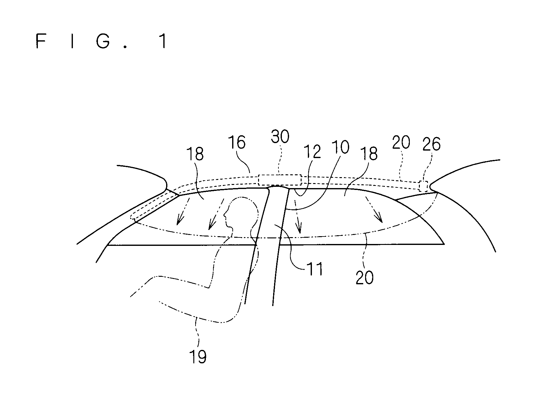
[0030]First, the development restricting member of the curtain airbag and the mounting structure of the curtain airbag including this will be described. FIG. 1 is a view showing the mounting structure of a curtain airbag 20 assembled in a vehicle.

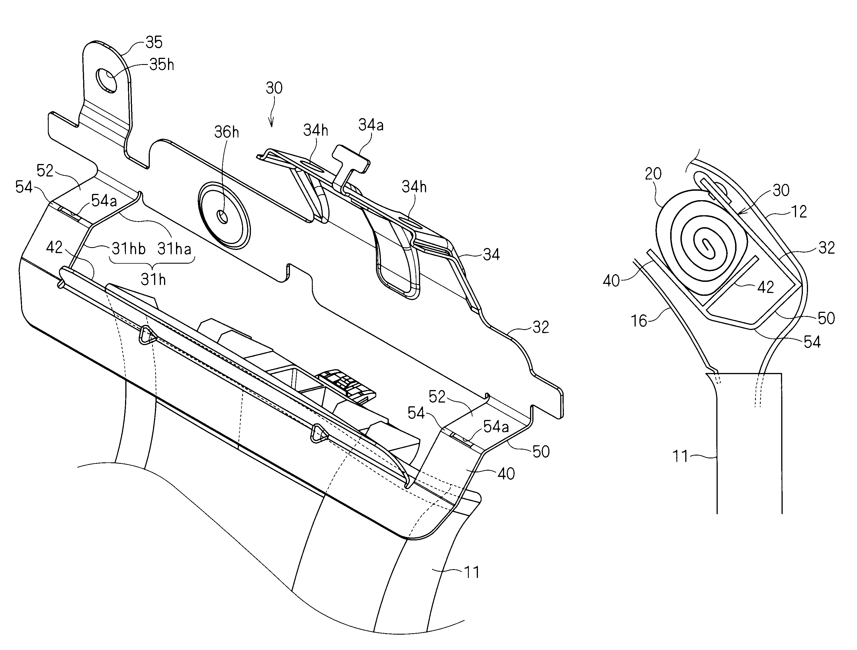
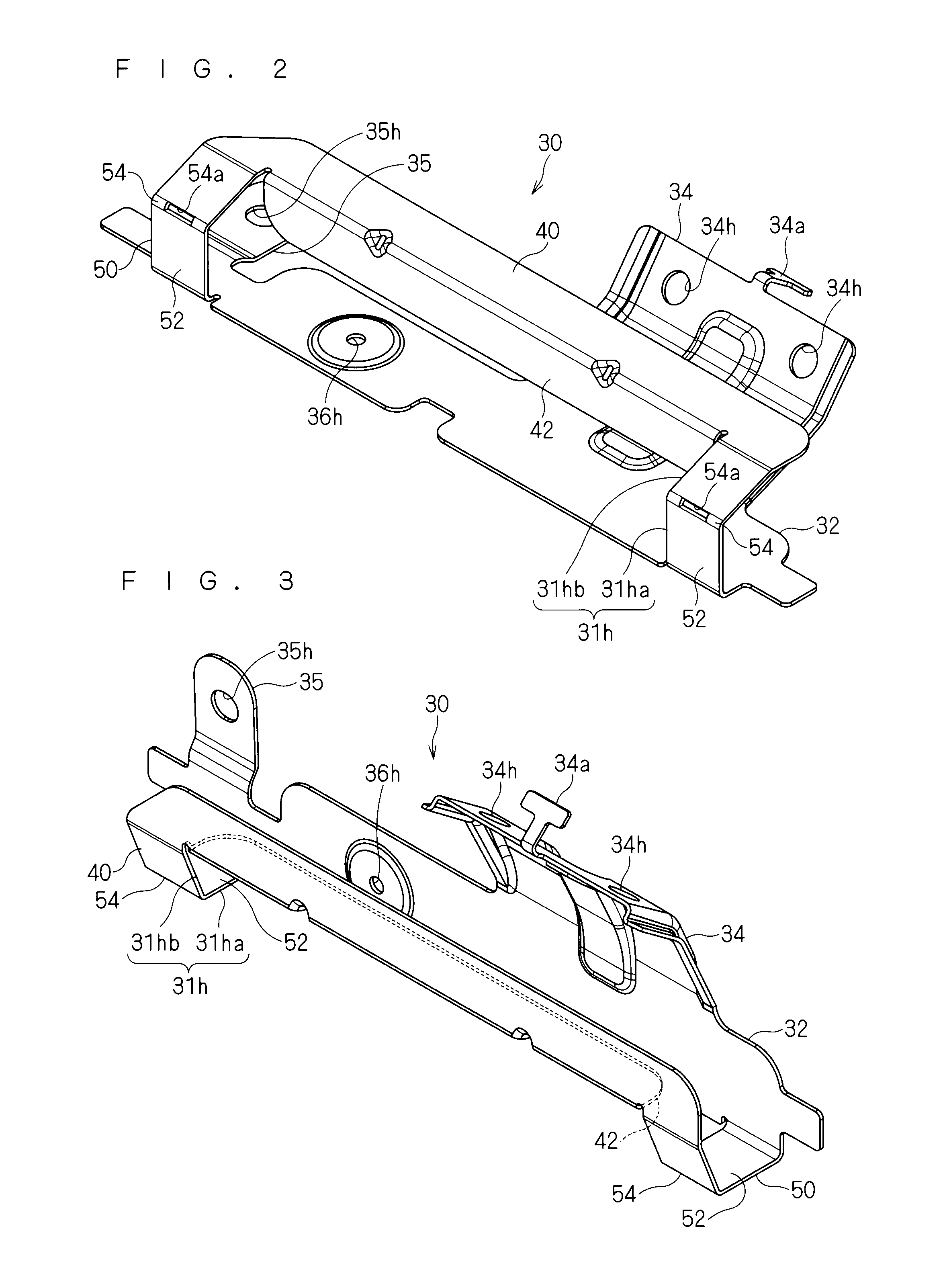
[0031]The mounting structure of this curtain airbag 20 is a structure attaching the curtain airbag 20 to the vehicle and restricting the developing operation thereof, including the curtain airbag 20, an inflator 26, and a development restricting member 30.

[0032]The curtain airbag 20 is formed to be flat sack-like with cloth and the like, and is configured to develop between a side window 18 of the vehicle and a head of a vehicle passenger 19 in a side collision of the vehicle. This curtain airbag 20 is mounted in the vehicle in the following manner.

[...


PUM


Abstract

A development restricting member is configured to include a fixing section attachable to a body of a vehicle above the pillar garnish, a holding section opposing to the fixing section, and a middle connecting section connecting a lower end part of the fixing section and a lower end part of the holding section, wherein an upstanding section is provided in a middle part of a base end part and a top end part of the holding section to extend toward the fixing section, so that a folded curtain airbag is housed so as to be surrounded by the fixing section, the holding section, and the upstanding section.

Description

TECHNICAL FIELD[0001]The present invention relates to a technology of restricting a developing operation of a curtain airbag developing in an emergency of a vehicle.BACKGROUND ART[0002]Conventionally, Patent Document 1 discloses a mounting structure of a curtain airbag device.[0003]The mounting structure of the curtain airbag device disclosed in Patent Document 1 includes a metal plate attached to a body of a vehicle and a guide plate arranged in the metal plate. A sectional shape of the guide plate viewed from the front of the vehicle is a U-shape wrapping around an envelope of a folded curtain airbag with an opening pointed toward outside the vehicle. In an inner wall surface of this guide plate, a plurality of trenches are formed so as to be substantially parallel along a longitudinal direction, and the guide plate is easily bent by these trenches. Then, the guide plate being subjected to a developing force of the curtain airbag is bent at each trench so as to fill a clearance of...

Claims


Application Information

Patent Timeline
Patent Type & Authority Patents(United States)
IPC IPC(8): B60R21/16B60R21/213B60R21/215B60R21/20
CPCB60R21/213B60R2021/161B60R21/232
Inventor SHIMAZAKI, YOSHIOHASHIZUME, TOMOKI
Owner ASHIMORI INDS
Why Eureka
Try Eureka