Drive apparatus for bidet toilet

a technology of drive apparatus and bidet, which is applied in the field of toilets, can solve the problems of prone to wear of gears, complicated arrangement, and high cos

Inactive Publication Date: 2012-10-23
JOHNSON ELECTRIC SA
View PDF10 Cites 16 Cited by
  • Summary
  • Abstract
  • Description
  • Claims
  • Application Information

AI Technical Summary

Problems solved by technology

The arrangement is complicated and the cost is high.
Furthermore, the gears are prone to be worn out and noise generated by the gears is great.

Method used


Image

  • Drive apparatus for bidet toilet
  • Drive apparatus for bidet toilet
  • Drive apparatus for bidet toilet

Examples


Embodiment Construction

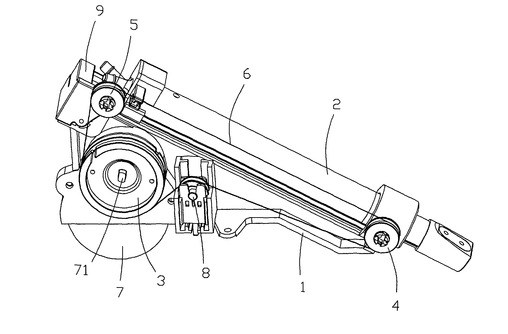
[0023]FIG. 1 illustrates a drive apparatus for driving a nozzle of a bidet toilet in accordance with a preferred embodiment of the present invention. The drive apparatus comprises a base 1 configured to be fastened within a toilet pedestal (not shown) of the toilet, a nozzle 2 having a nozzle head with at least one water discharge port, a driving wheel 3, a pair of guide wheels 4 and 5, a conveyer in the form of a string 6, a motion output device 7, a tensioner 8, and a frame 9. The driving wheel 3, guide wheels 4 and 5, string 6, tensioner 8 and frame 9 convert the rotating motion of the output shaft 71 of the motion output device 7 into linear motion of the nozzle 2. The motion output device 7 comprises a stepping motor and a gearbox with an output shaft 71.

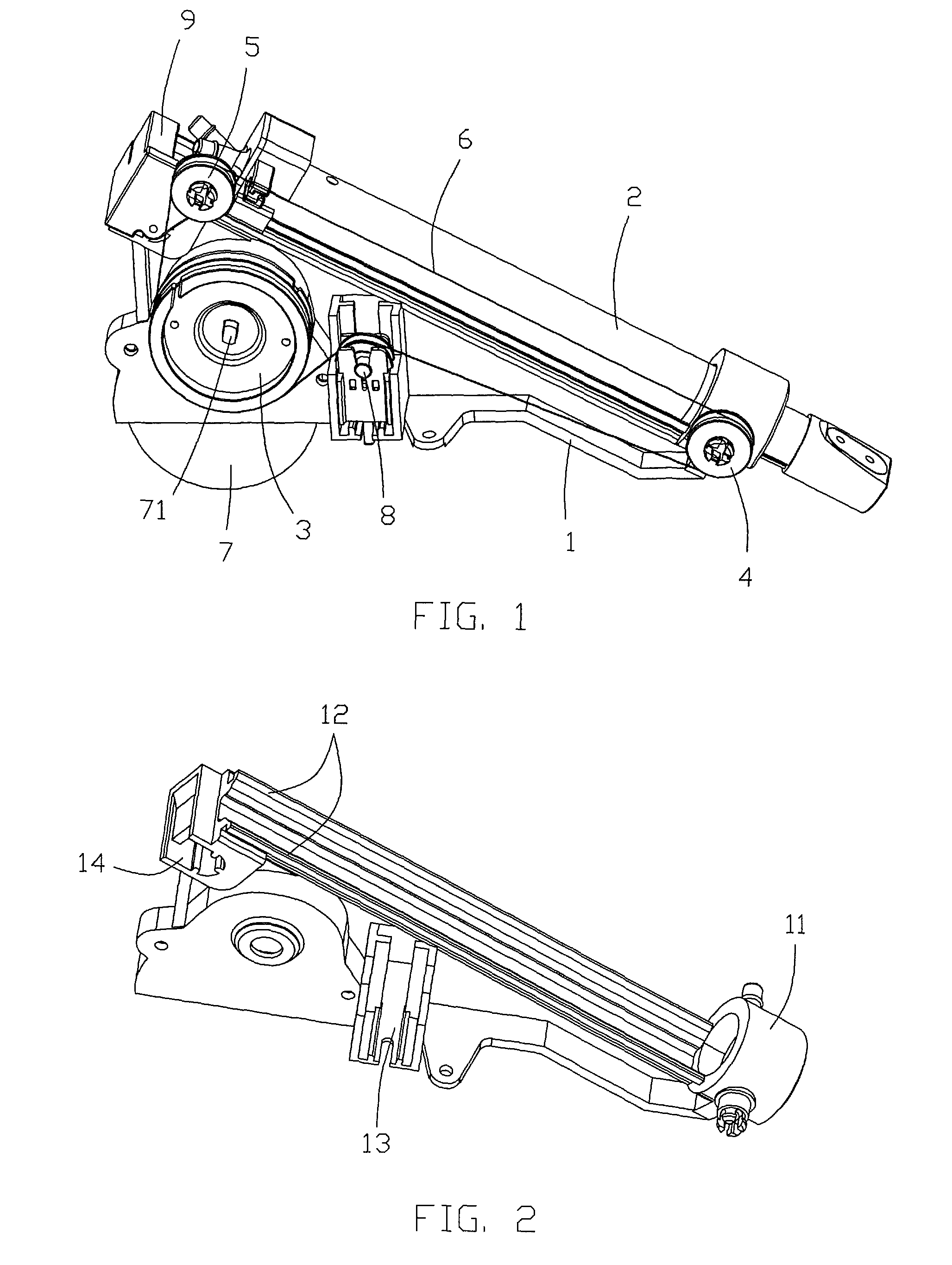
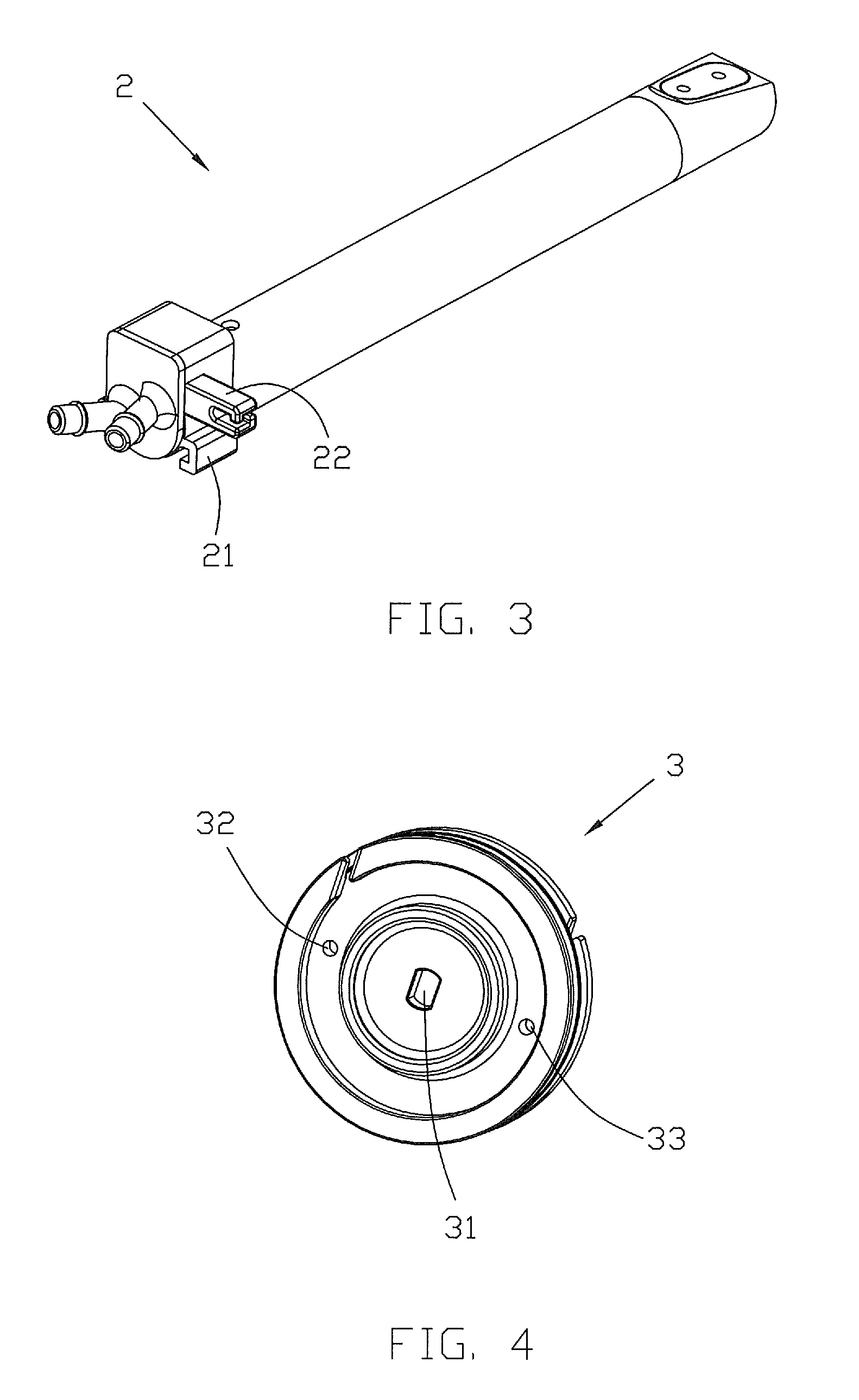
[0024]Referring to FIGS. 2 and 3, the base 1 comprises a collar 11 for slidably supporting and guiding the nozzle 2, and a pair of guide rails 12 for slidably engaging with a pair of guide slots 21 formed on the nozzle 2 to gui...


PUM


Abstract

Apparatus for driving a nozzle of a bidet toilet, has a base 1; a nozzle 2; a guide device 11, 12 formed on the base for guiding linear movement of the nozzle; a motion output device 7 having an output shaft 71; a driving wheel 3 attached to the output shaft and being rotatably driven with the output shaft; a pair of guide wheels 4,5 rotatably fixed relative to the base, and a non-toothed conveyer 6 wound around the driving wheel 3 and the guide wheels 4, 5 and fastened to the nozzle 2. Rotation of the driving wheel 3 causes linear movement of the nozzle 2.

Description

CROSS REFERENCE TO RELATED APPLICATIONS[0001]This non-provisional patent application claims priority under 35 U.S.C. §119(a) from Patent Application No. 200810142503.7 filed in The People's Republic of China on Jul. 23, 2008.FIELD OF THE INVENTION[0002]This invention relates to toilets and in particular, to a drive apparatus for a bidet toilet.BACKGROUND OF THE INVENTION[0003]Bidet toilets have become widely used. A bidet toilet has a retractable wand or nozzle through which washing water is sprayed out for washing the “bottom” and the like of a user sitting on a seat of the toilet. A drive apparatus is used to move the nozzle along a linear path between an active position where it is extended or use and a retracted position. The apparatus includes a motor which has a rotating output shaft which is connected to the nozzle through a number of gears and a rack to drive the nozzle by a rack and pinion type arrangement. The arrangement is complicated and the cost is high. Furthermore, t...

Claims


Application Information

Patent Timeline
Patent Type & Authority Patents(United States)
IPC IPC(8): A47K3/022
CPCE03D9/08
Inventor PAN, JI CHENGLI, FEISONG, YONG QIANGPENG, GANGWU, ZHI QIANG
Owner JOHNSON ELECTRIC SA
Why Eureka
Try Eureka