Patient interface systems
a patient interface and patient technology, applied in the field of patient interface systems, can solve the problems of patients who may snore, may not be suitable for treatment using closed pap methods, mild or moderate cases of sdb, and may not gain a significant benefit from the use of closed pap treatmen
- Summary
- Abstract
- Description
- Claims
- Application Information
AI Technical Summary
Benefits of technology
Problems solved by technology
Method used
Image
Examples
first embodiment
1.1.1 Mechanical Fixation First Embodiment
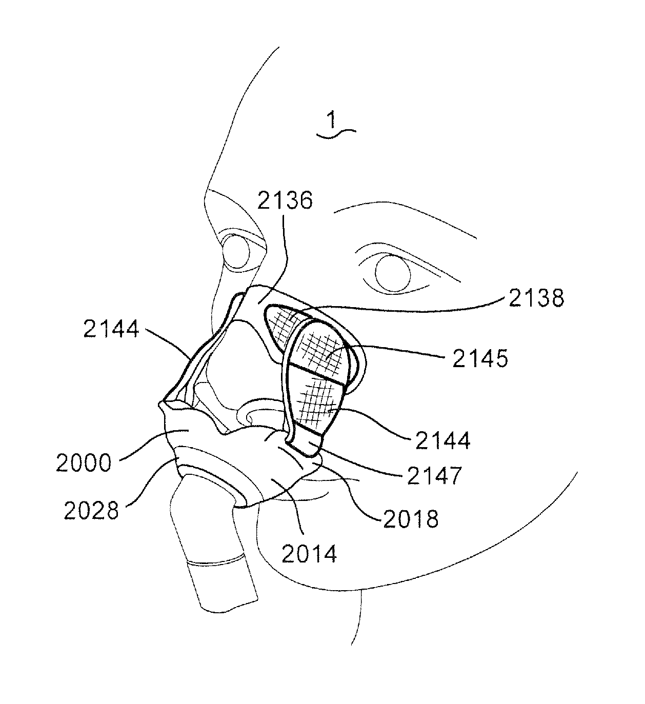
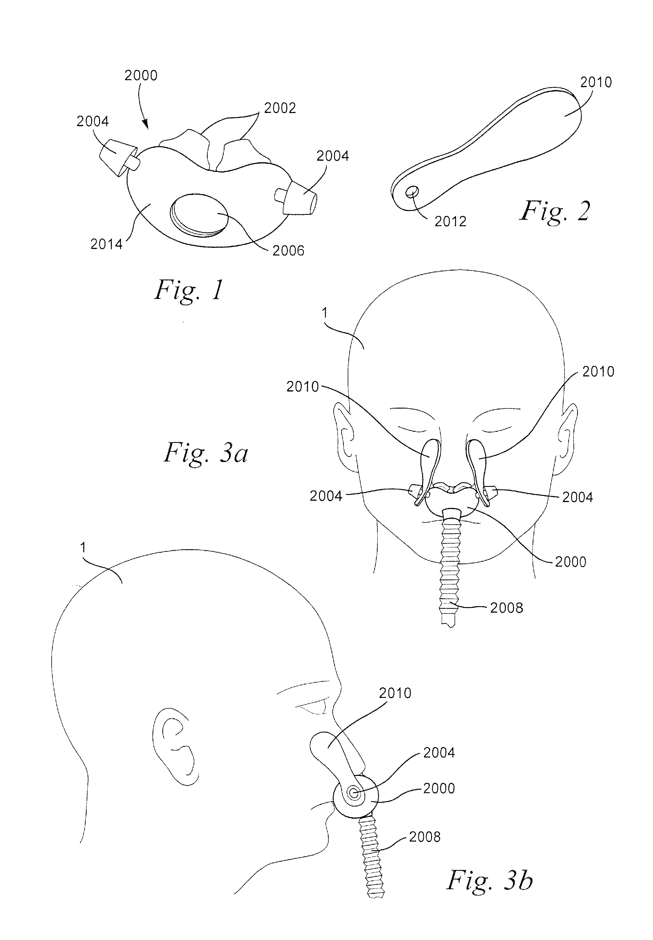
[0124]Referring to FIGS. 1-3b, a patient interface structure may comprise a patient interface structure, e.g. a cushion, 2000 comprising nasal pillows, puffs, or prongs 2002. The patient interface structure 2000 may also comprise tabs, or studs, 2004 at opposite ends of a base portion 2014. The patient interface structure 2000 may further include an aperture 2006 configured to allow for connection of a tube, hose, or conduit 2008. The tube 2008 may be, for example, a retractable tube, such as disclosed in U.S. Patent Application Publication 2009 / 0078259 A1, the entire contents of which are incorporated herein by reference.
[0125]The studs 2004 are each configured to be connected to a patient adhesive strip 2010 that includes a hole 2012 at a first end. The studs 2004 are inserted through the holes 2012 of the patient adhesive strip 2010 to secure the patient adhesive strips 2010 to the patient interface structure. The top portion of stud 2004...
second embodiment
1.1.2 Mechanical Fixation Second Embodiment
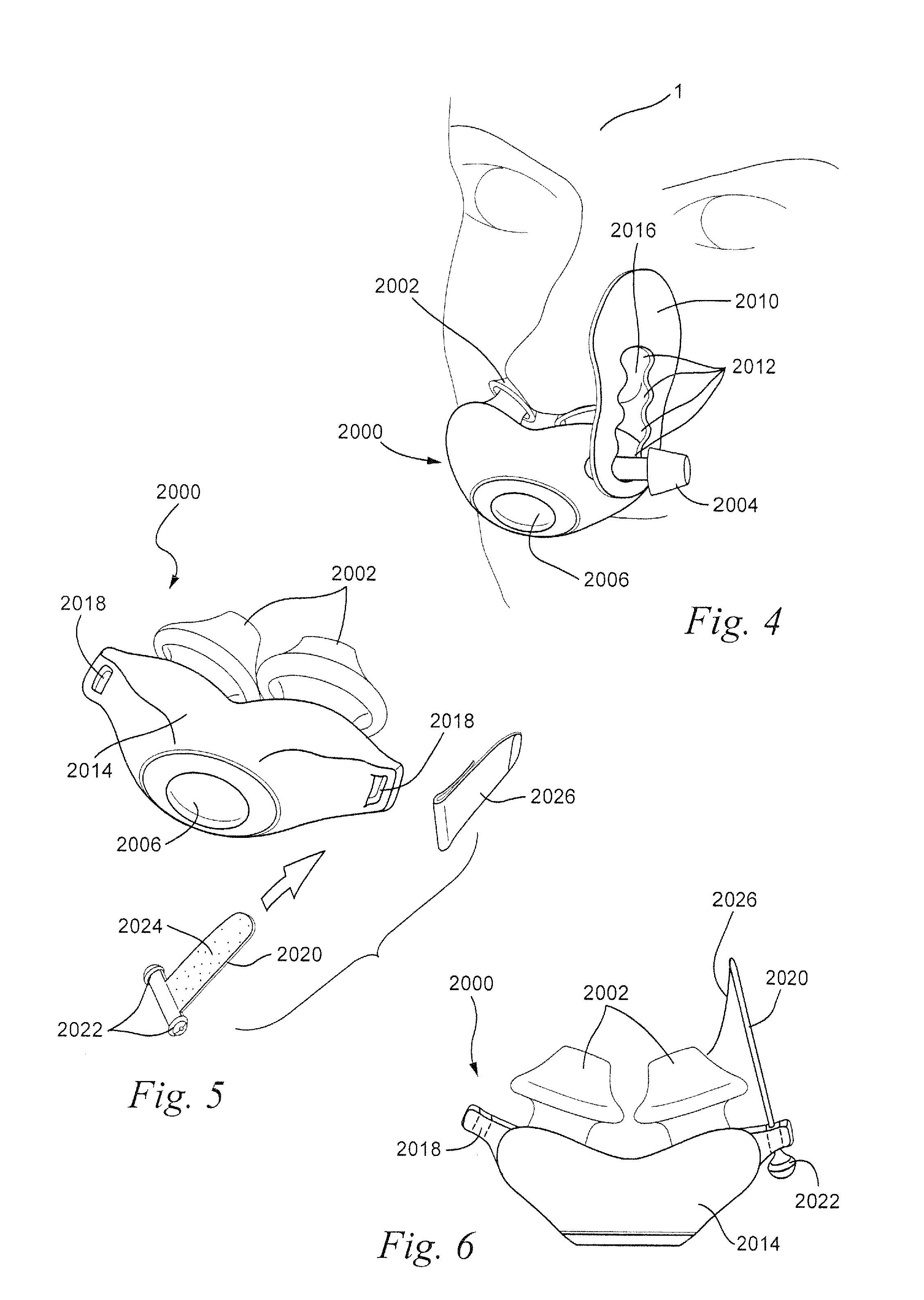
[0129]Referring to FIG. 4, the patient adhesive strips 2010 (only one shown) may include a plurality of holes or spacings 2012 that are each configured to accept the tab or stud 2004 of the patient interface structure 2000. As shown in FIG. 4, the plurality of holes 2012 are joined by a channel 2016 formed in the patient adhesive strip 2010 that permits the stud 2004 to be disengaged from one hole and engaged with another hole without completely disengaging the patient adhesive strip 2010 from the stud 2004. The stud 2004 may be disengaged from one hole 2012 and engaged with another hole 2012 to permit adjustment of the position of the patient adhesive strip 2010 without completely disengaging the adhesive strip 2010 from the patient interface structure 2000. It should be appreciated that the holes 2012 of the patient adhesive strip 2010 may be formed separately, i.e. without a channel, so that adjustment of the position of the patient adhe...
third embodiment
1.1.3 Mechanical Fixation Third Embodiment
[0130]Referring to FIGS. 5-7, the patient interface system may comprise a patient interface structure 2000 provided with loops 2018 on opposite sides of the patient interface structure 2000. Patient adhesive strips 2020 (only one shown) may be inserted through the loops 2018 and locked in place on the patient interface structure 2000 by locking tabs 2022. The locking tabs 2022 may be rigid or semi-rigid (for example, silicone, polycarbonate, polypropylene, thermoplastic elastomers (TPE), etc.) and are provided to the adjoining ends of the patient adhesive strips 2020. The adhesive 2024 of the patient adhesive strips 2020 may be covered by, for example, release paper 2026 to allow the patient adhesive strips 2020 to be inserted through the loops 2018 so that the patient adhesive strips 2020 can be pulled through the loops 2018 until the locking tabs 2022 engage with the loops 2018.
[0131]The locking tabs 2022 may be molded onto the patient adh...
PUM
 Abstract
Description
Claims
Application Information
 - R&D
- Intellectual Property
- Life Sciences
- Materials
- Tech Scout
- Unparalleled Data Quality
- Higher Quality Content
- 60% Fewer Hallucinations
Browse by: Latest US Patents, China's latest patents, Technical Efficacy Thesaurus, Application Domain, Technology Topic, Popular Technical Reports.
© 2025 PatSnap. All rights reserved.Legal|Privacy policy|Modern Slavery Act Transparency Statement|Sitemap|About US| Contact US: help@patsnap.com


