
Eureka
For R&D, Eureka makes reading and utilizing patents & technical documents easy.
Eureka AIR
Designed for self-driven R&D workflows. Generate viable solutions, solve complex R&D challenges, empower your innovation with AI.

Eureka Materials
Designed for material experts only. Revolutionize your material R&D, from search, analyze, to developing new materials.

TechResearch
Generate reliable direction feasibility study reports for your R&D in just a few steps.

TechSeek
Discover and master advanced knowledge NOW. Basics, ideas, possibilities, all at once.

TechMind
As an expert in R&D Theories, TechMind can generates customized viable solutions instantly.

TechRisk
Analyze your overall solution with one click, know your potential R&D risks in advance.

TechMonitor
Get weekly tech updates, stay abreast of the latest tech innovations and key insights.
Electromagnetic coupling device
a technology of electromagnetic coupling and coupling element, which is applied in the direction of magnetically actuated clutches, mechanical actuators, mechanical apparatus, etc., can solve the problems of heat deformation of the sealed resin of the package portion, heat deformation of the circuit of the diode element, and increase of the heat load of the diode, so as to reduce the heat load, easy waterproof the diode, and broaden the storage space
- Summary
- Abstract
- Description
- Claims
- Application Information
AI Technical Summary
Benefits of technology
Problems solved by technology
Method used
Image

Examples
first embodiment
(First Embodiment)
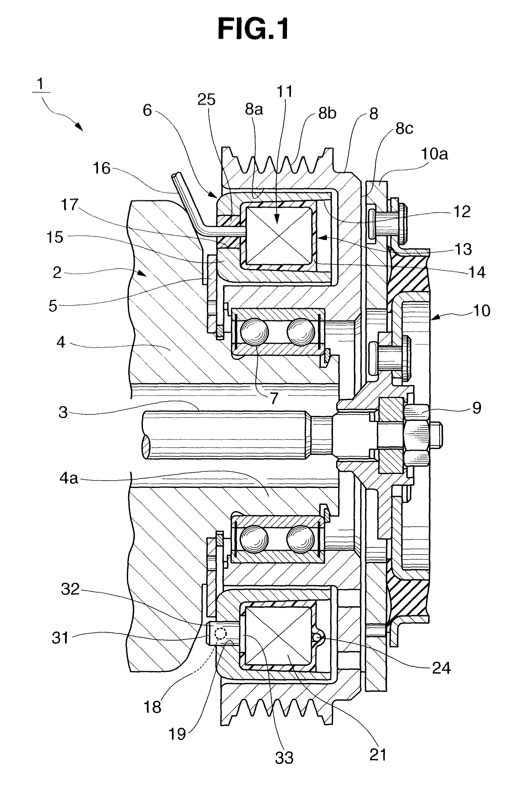
[0054]An embodiment of an electromagnetic coupling device according to the present invention will be described in detail below with reference to FIGS. 1 to 12. This embodiment will exemplify a case in which the present invention is applied to an electromagnetic clutch.
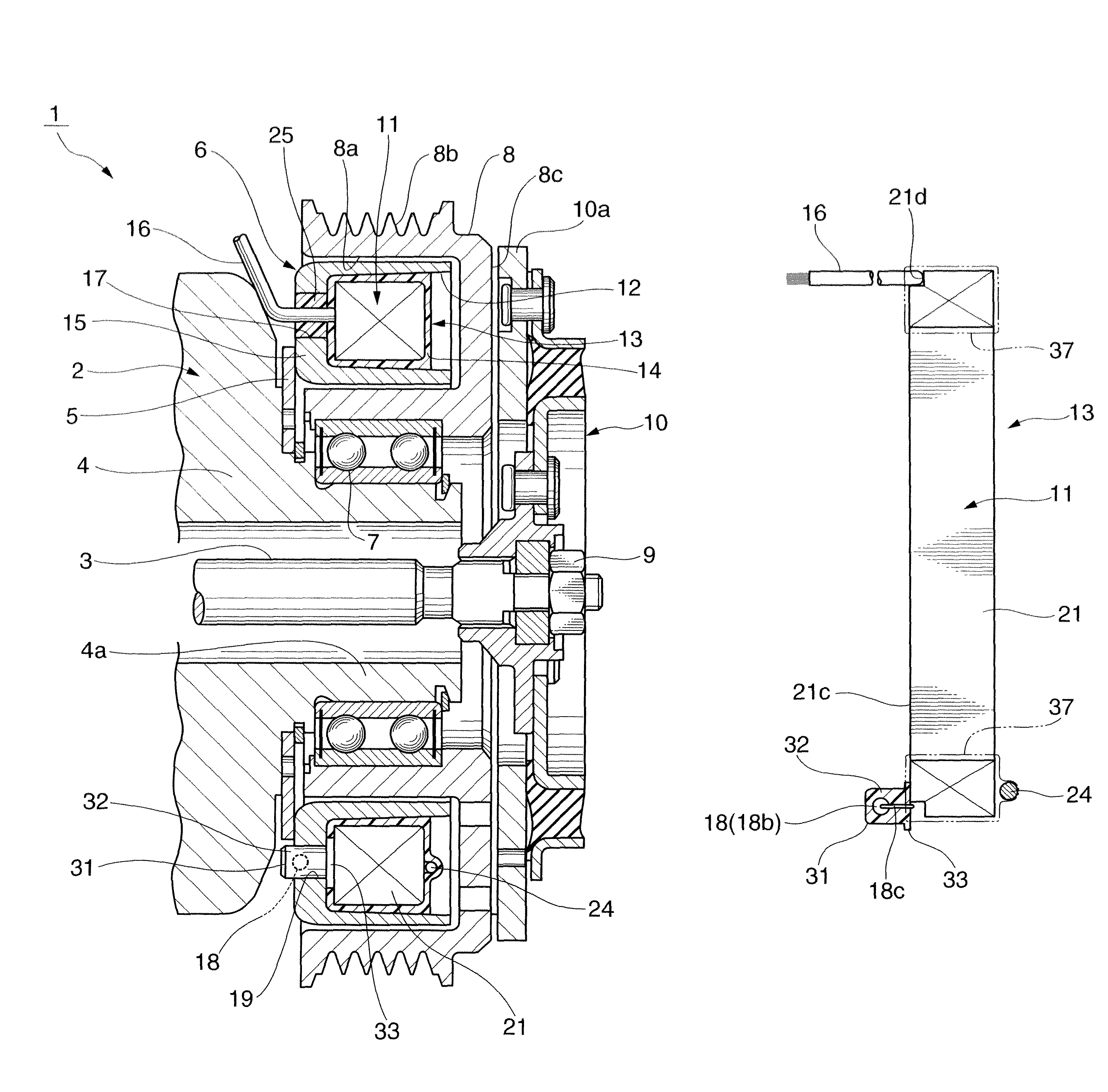
[0055]An electromagnetic clutch 1 shown in FIG. 1 serves to transfer power to a rotating shaft 3 of a car air conditioner compressor 2 or shut off the transfer of power. The electromagnetic clutch 1 includes a field core 6 fixed to a front housing 4 of the compressor 2 through a mounting plate 5. The electromagnetic clutch 1 includes a rotor 8 rotatably supported on a cylindrical portion 4a of the front housing 4 through a bearing 7. The electromagnetic clutch 1 includes an armature assembly 10 which is spline-fitted to the rotating shaft 3 and secured with a nut 9.
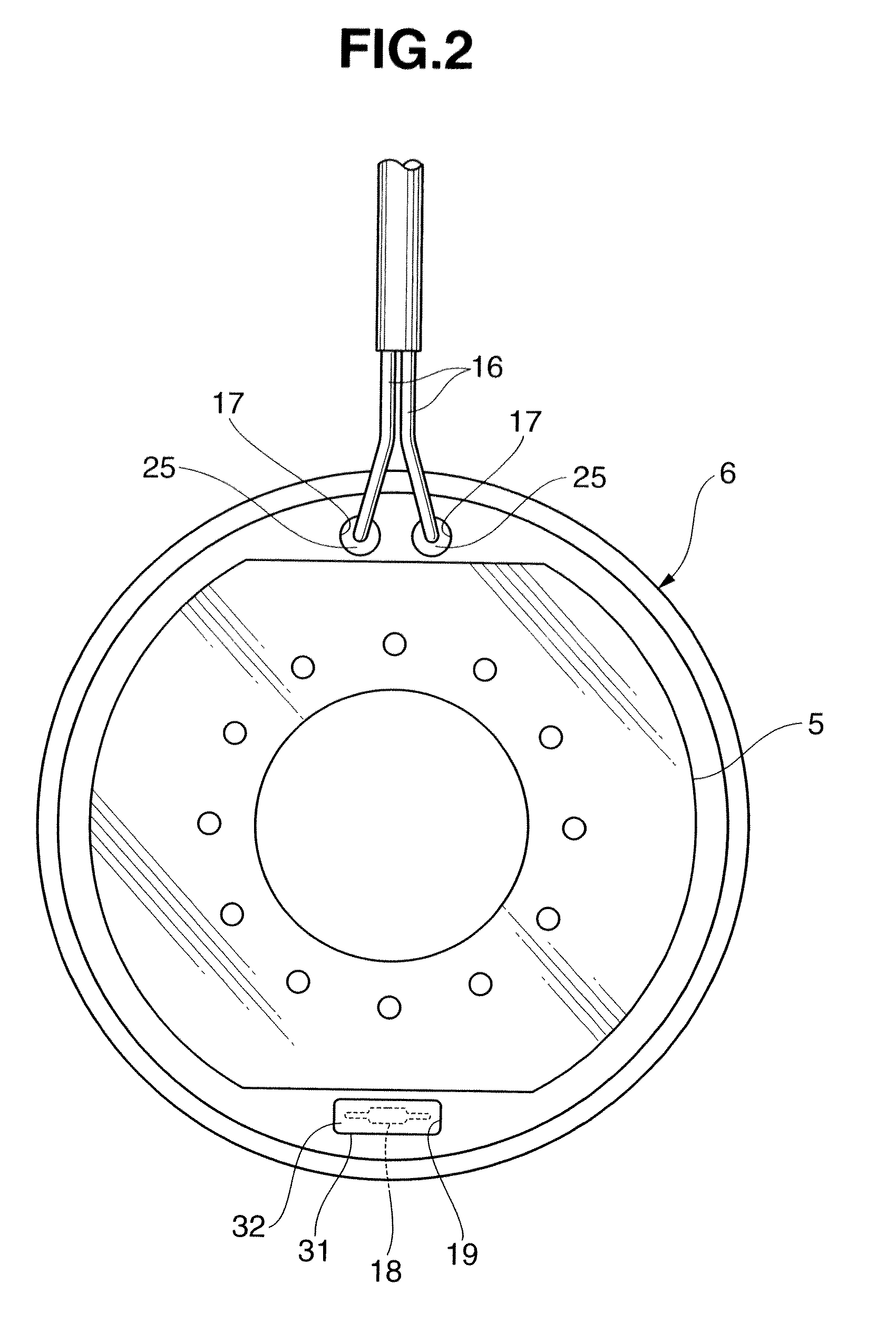
[0056]The field core 6 has an annular shape as a whole and is positioned on the same axis as that of the rotating shaft 3. The field core ...
second embodiment
(Second Embodiment)
[0098]The electromagnetic coupling device according to the present invention can be configured as shown in FIGS. 13 to 22. The same reference numerals as in FIGS. 1 to 12 denote the same or similar members in FIGS. 13 to 22, and a detailed description of the members will be omitted, as needed.
[0099]A field core 6 shown in FIG. 13 is mounted in an electromagnetic clutch to transfer and disconnect power to a car air conditioner compressor 2. A portion other than the field core 6 of the electromagnetic clutch can employ the same arrangement as that of the electromagnetic clutch 1 described in the first embodiment.
[0100]As shown in FIG. 13, the field core 6 according to this embodiment employs a structure in which lead wires 16 and an insulating bush 31 are located at the same position. The lead wires 16 are guided outside the field core 6 through the insulating bush 31. That is, the lead wires 16 are guided outside the field core 6 through a through hole 41 of the fi...
third embodiment
(Third Embodiment)
[0114]An electromagnetic coupling device according to the present invention can have arrangements like those shown in FIGS. 23 to 27. The same reference numerals as in FIGS. 1 to 22 denote the same or similar members in FIGS. 23 to 27, and a detailed description of the members will be omitted, as needed.
[0115]A field core 6 shown in FIG. 23 is mounted in a body earth type electromagnetic coupling device. This electromagnetic coupling device can employ the same arrangement as that of the electromagnetic clutch 1 described in the first or second embodiment except for the field core 6.
[0116]The field core 6 shown in FIG. 23 includes one lead wire 16 and one body earth wire 51. The lead wire 16 and body earth wire 51 are guided outside the field core 6 through an insulating bush 31. The insulating bush 31 is equivalent to the insulating bush 31 described in the second embodiment.
[0117]An earth terminal 52 is fixed to the distal end portion of the body earth wire 51 by ...
PUM
| Property | Measurement | Unit |
|---|---|---|
| voltage | aaaaa | aaaaa |
| surge voltage | aaaaa | aaaaa |
| shape | aaaaa | aaaaa |
Abstract
Description
Claims
Application Information
 - R&D Engineer
- R&D Manager
- IP Professional
- Industry Leading Data Capabilities
- Powerful AI technology
- Patent DNA Extraction
Browse by: Latest US Patents, China's latest patents, Technical Efficacy Thesaurus, Application Domain, Technology Topic, Popular Technical Reports.
© 2024 PatSnap. All rights reserved.Legal|Privacy policy|Modern Slavery Act Transparency Statement|Sitemap|About US| Contact US: help@patsnap.com