System and method of video data encoding with minimum baseband data transmission

a video data and data transmission technology, applied in the field of display video, can solve the problems of limiting the communication bandwidth of the display device, affecting the satisfaction of these increasing user desires, and their own problems, so as to improve the effective refresh rate, minimize the bandwidth required, and boost the display frame rate

Inactive Publication Date: 2012-10-23
SONY CORP +1
View PDF10 Cites 0 Cited by
  • Summary
  • Abstract
  • Description
  • Claims
  • Application Information

AI Technical Summary

Benefits of technology

[0016]The present invention relates to a method for minimizing the bandwidth required to drive high frame rate displays by performing the up-conversion of data at the point of actual display; as contrasted to up-converting the video and sending the high-bandwidth up-converted video to the display device. This method overcomes the shortcomings with frame rate converters as it does not need to “guess” (make unwarranted estimates) at how the intermediate frames should be represented, and does not require extensive video processing. All related processing, including the making of any assumptions, within the present invention are performed during tagging at a stage in the video processing where the “raw” data is available, this raw data can include any additional inputs as desired. To improve the effective refresh rate, and thus motion perception, display frame rates are boosted by variously synthesizing intermediate frames based on information tags along with video data in the bounding real frames.
[0028]It will be appreciated that the inclusion of tag information allows the up-conversion process to be dynamically reconfigured and pixel displacements manipulated when generating intermediate frames. The up-conversion is performed after receipt of the tagged video, such as within a display device, or more preferably within the timing controller of the destination display device. In at least one implementation, pixels are output to a gamma corrector for immediate display on the screen of the destination display device. Tag information is preferably communicated to the destination display within the video stream itself, such as contained within at least one pseudo pixel following the frame synchronization bit, thus alleviating the need for synchronization constructs which would be required if the tag information were retained in a separate stream.
[0035]An aspect of the invention is a method and apparatus for increasing display refresh rates without the need for substantially increasing video bandwidth to the display device.
[0036]Another aspect of the invention provides a means for boosting display frame rates in response to the generation of intermediate video frames.
[0046]Another aspect of the invention provides for increasing refresh rates by agglomerating tag information with the video for use in dynamically configuring the up-converter and manipulating pixel displacements for synthesized (intermediate) frames.
[0048]Another aspect of the invention is a method of increasing display refresh rates for use with a variety of display devices.

Problems solved by technology

However, the limits of communication bandwidth to the display device often impairs satisfying these increasing user desires.
Non-CRT display technologies each have their own issues in regard to refreshing.
These converters attempt to glean information from the transmitted video stream which requires substantial video processing capability while often introducing artifacts into the final picture.
In particular, frame rate converters suffer the most when the video includes elements such as closed captioning, subtitles, Really-Simple-Syndication (RSS) feeds, picture-in-picture, and so forth that can not be estimated properly from adjacent frames.

Method used


Image

  • System and method of video data encoding with minimum baseband data transmission
  • System and method of video data encoding with minimum baseband data transmission
  • System and method of video data encoding with minimum baseband data transmission

Examples


Embodiment Construction

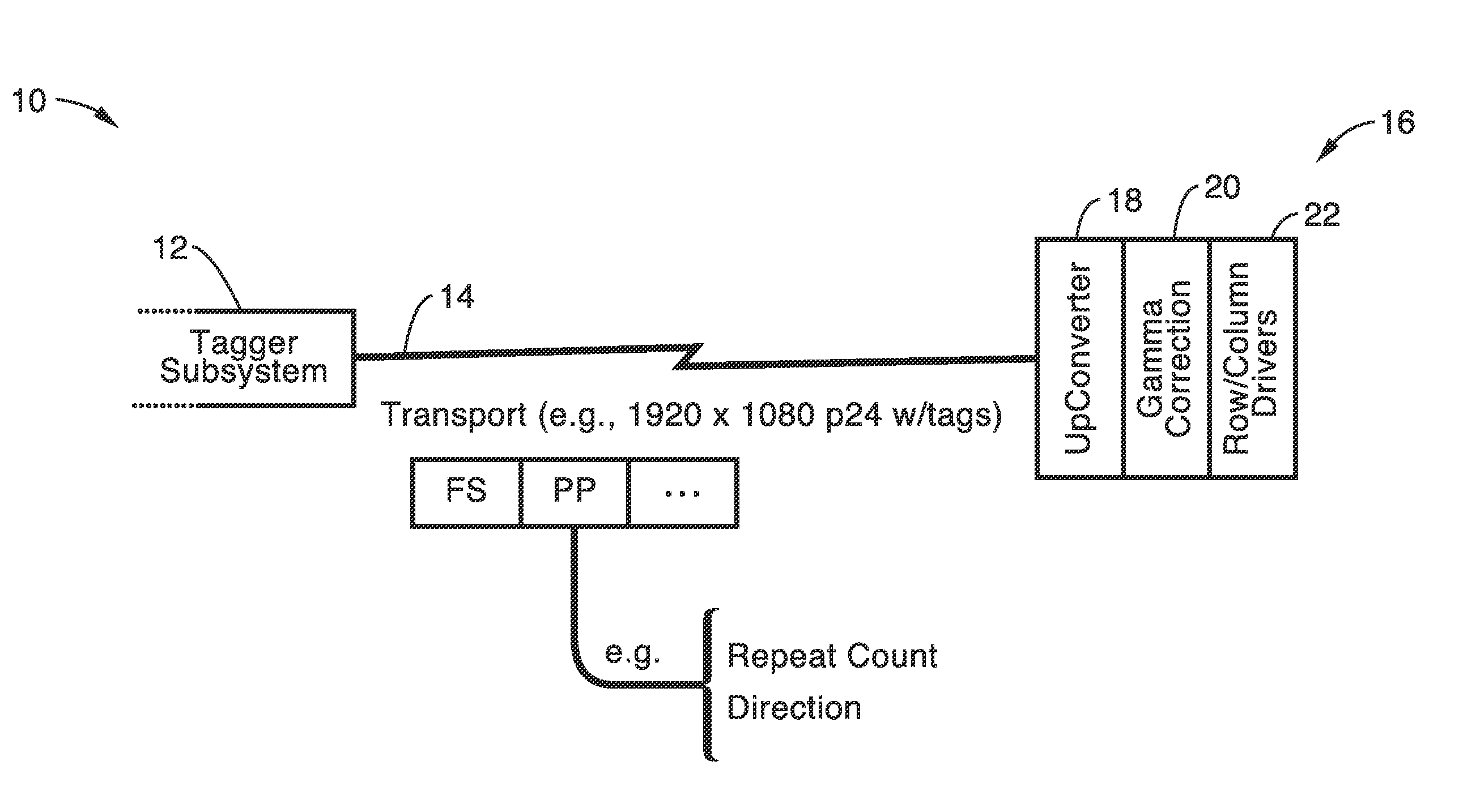
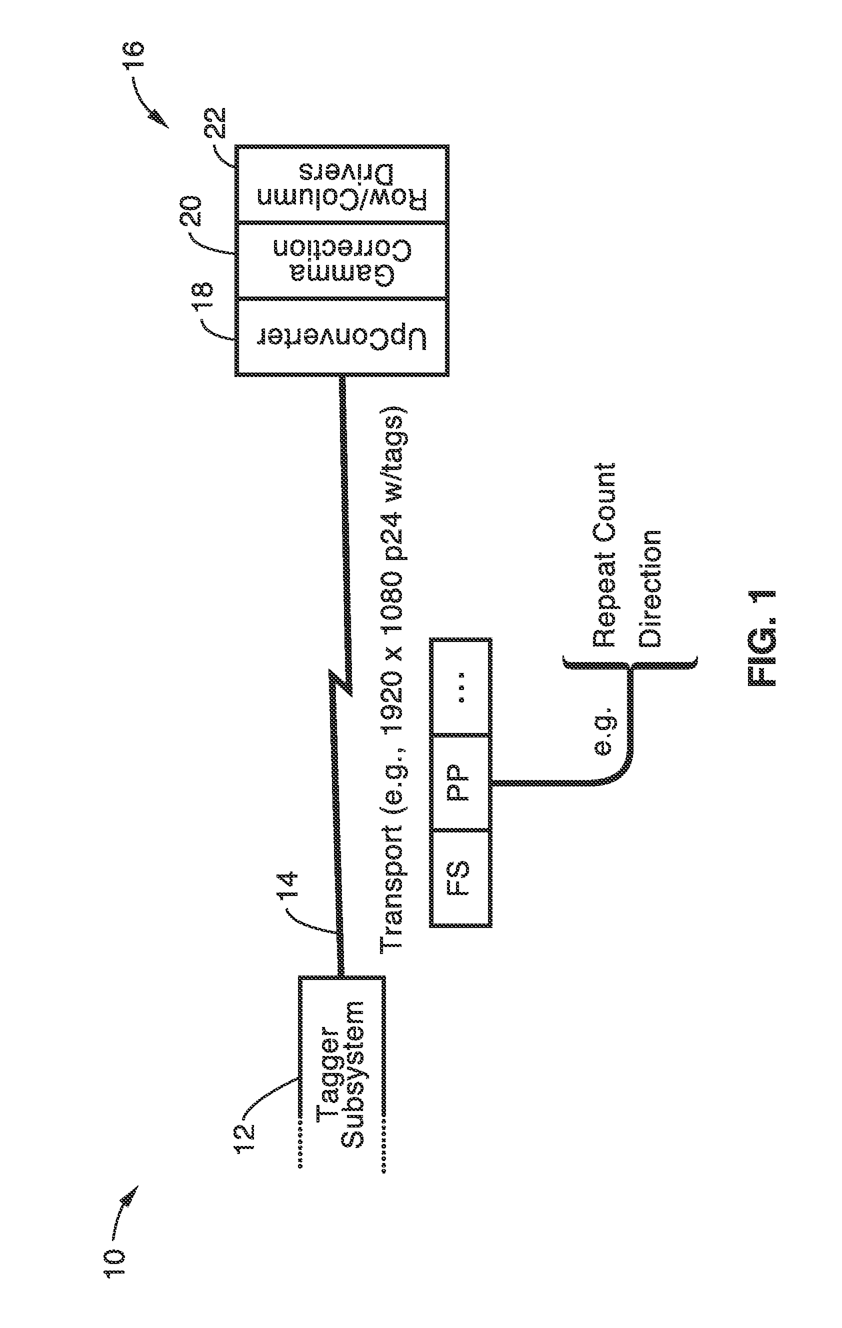
[0059]Referring more specifically to the drawings, for illustrative purposes the present invention is embodied in the apparatus generally shown in FIG. 1 through FIG. 6. It will be appreciated that the apparatus may vary as to configuration and as to details of the parts, and that the method may vary as to the specific steps and sequence, without departing from the basic concepts as disclosed herein. Tables are included at the end of this specification.

[0060]1. Introduction.

[0061]A method of video data encoding and processing to drive high frame rate displays while necessitating only a minimum baseband data transmission that includes information tags. This invention relies on frame and pixel tags to minimize the amount of data that needs to be transported to a display device while still providing detailed control of the up-conversion process.

[0062]As the present invention is preferably utilized for minimizing video bandwidth communicated into the midst of the video display device, i...


PUM


Abstract

Just-in-time up-conversion utilizes frame tagging, and optionally pixel tagging, to minimize the data bandwidth required to drive a display. According to this approach video is maintained in its native frame rate until needed in the display device, such as for pixel control at the row / column drivers. By way of example, a frame tag comprises a repeat count and direction information upon which display refresh is based. In addition, pixel tagging can be utilized to dynamically configure the up-converter to generate pixel displacements within synthesized intermediate frames, such as based on different pixel layer representations. The data stream can utilize traditional fixed pixel lengths or variable pixel lengths to conserve additional bandwidth.

Description

CROSS-REFERENCE TO RELATED APPLICATIONS[0001]Not ApplicableSTATEMENT REGARDING FEDERALLY SPONSORED RESEARCH OR DEVELOPMENT[0002]Not ApplicableINCORPORATION-BY-REFERENCE OF MATERIAL SUBMITTED ON A COMPACT DISC[0003]Not ApplicableNOTICE OF MATERIAL SUBJECT TO COPYRIGHT PROTECTION[0004]A portion of the material in this patent document is subject to copyright protection under the copyright laws of the United States and of other countries. The owner of the copyright rights has no objection to the facsimile reproduction by anyone of the patent document or the patent disclosure, as it appears in the United States Patent and Trademark Office publicly available file or records, but otherwise reserves all copyright rights whatsoever. The copyright owner does not hereby waive any of its rights to have this patent document maintained in secrecy, including without limitation its rights pursuant to 37 C.F.R. §1.14.BACKGROUND OF THE INVENTION[0005]1. Field of the Invention[0006]This invention pert...

Claims


Application Information

Patent Timeline
Patent Type & Authority Patents(United States)
IPC IPC(8): H04N7/081H04N7/24H04N7/01
CPCG06F3/1415G09G2310/04G09G2340/0435H04N7/01H04N7/0127
Inventor UNGER, BOB
Owner SONY CORP
Why Eureka
Try Eureka