Position indicating device

a technology of position indicating device and circuit breaker, which is applied in emergency protective devices, protective switch details, and switchgear with withdrawn carriage, etc., can solve the problem of difficulty in fast and precise recognition of the position of the circuit breaker main body

Active Publication Date: 2012-10-30
LG IND SYST CO LTD
View PDF13 Cites 1 Cited by
  • Summary
  • Abstract
  • Description
  • Claims
  • Application Information

AI Technical Summary

Benefits of technology

[0011]Therefore, in order to obviate the problem of the related art, an object of the present invention is to provide a position indicating device for a circuit breaker, by which a position of the circuit breaker can be identified fast and precisely.

Problems solved by technology

However, the position indication sticker is not easily viewed due to being obscured by the circuit breaker main body, which results in difficulty in the fast and precise recognition of the position of the circuit breaker main body.

Method used


Image

  • Position indicating device
  • Position indicating device
  • Position indicating device

Examples


embodiment

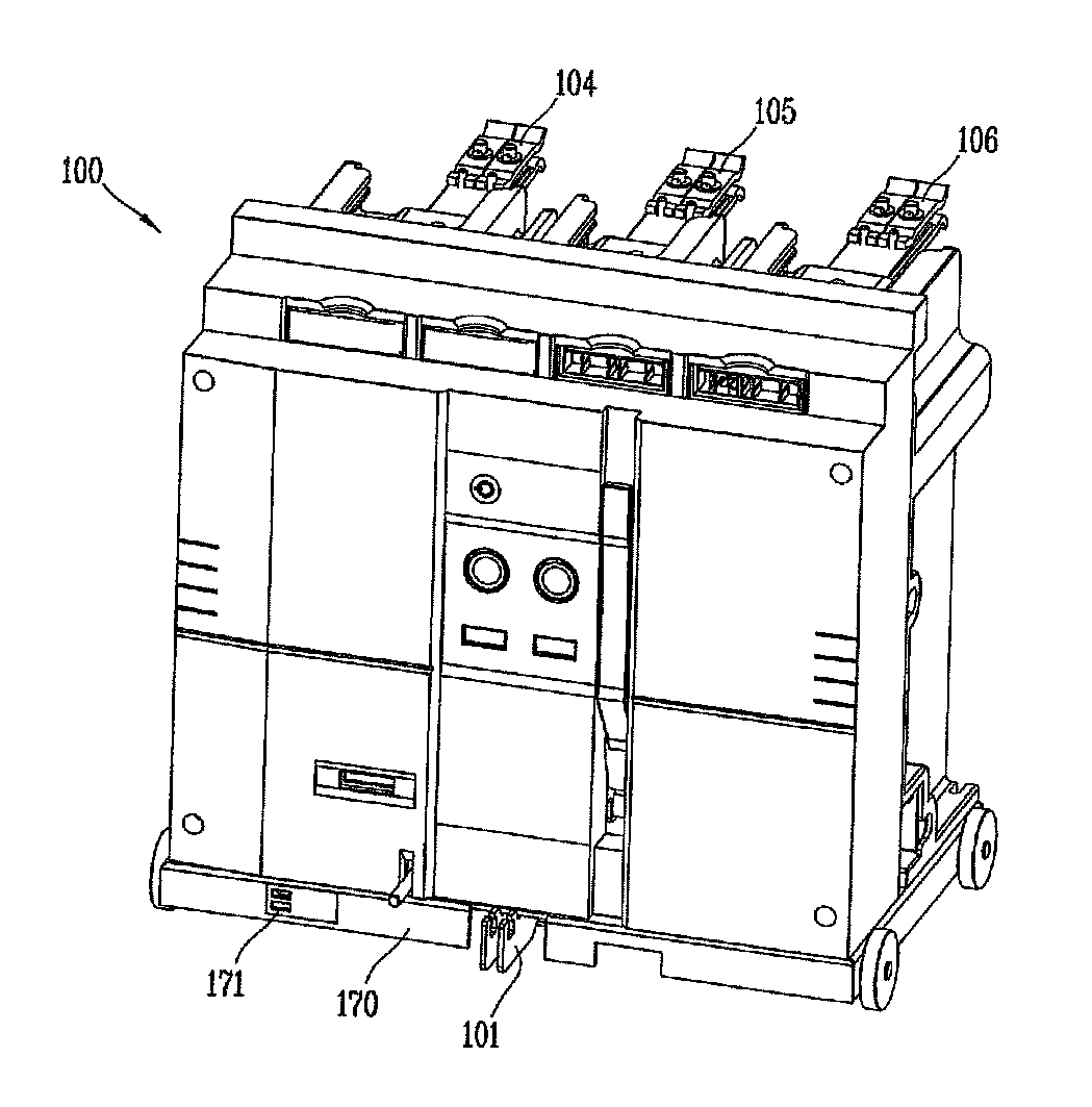
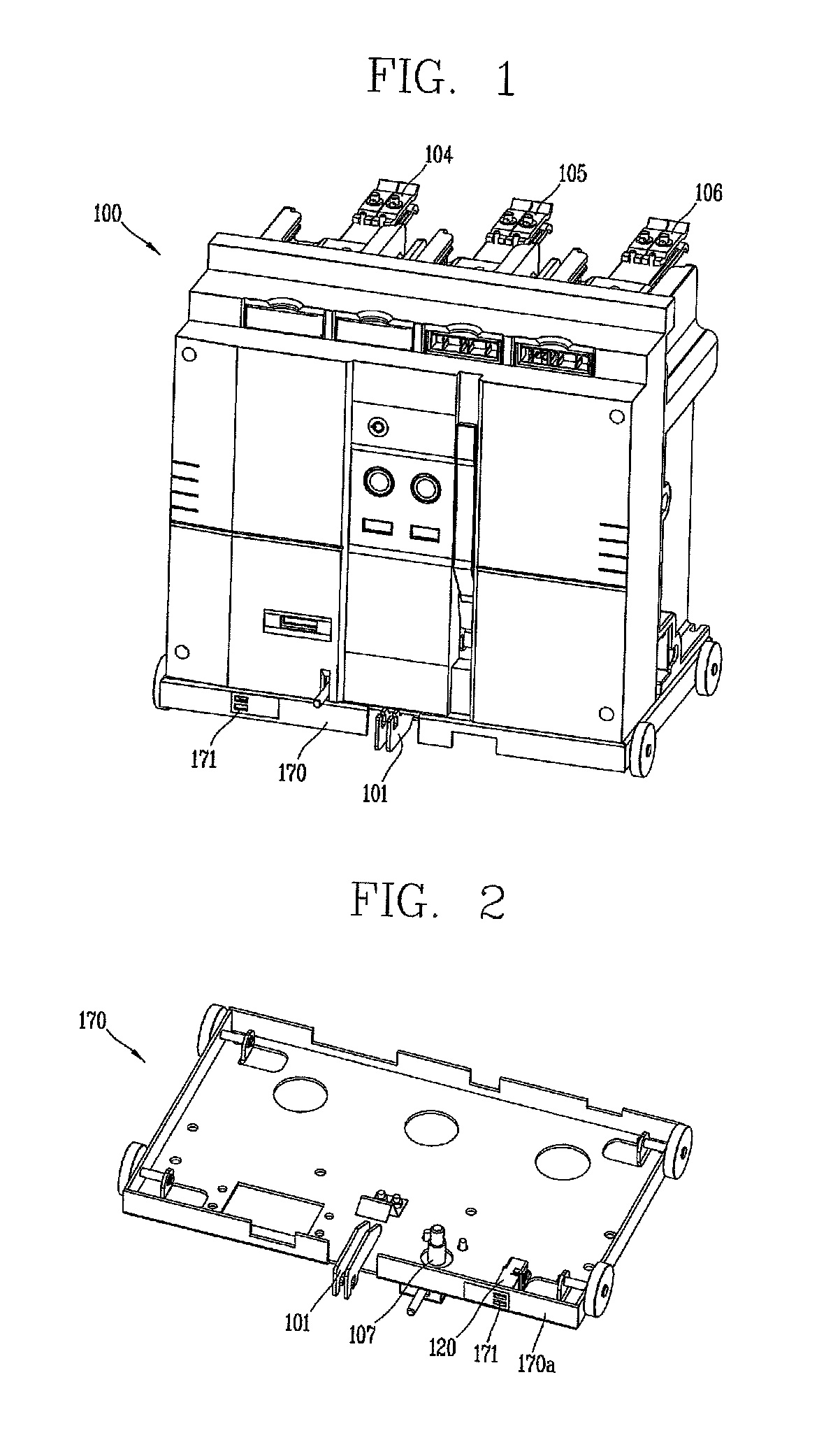
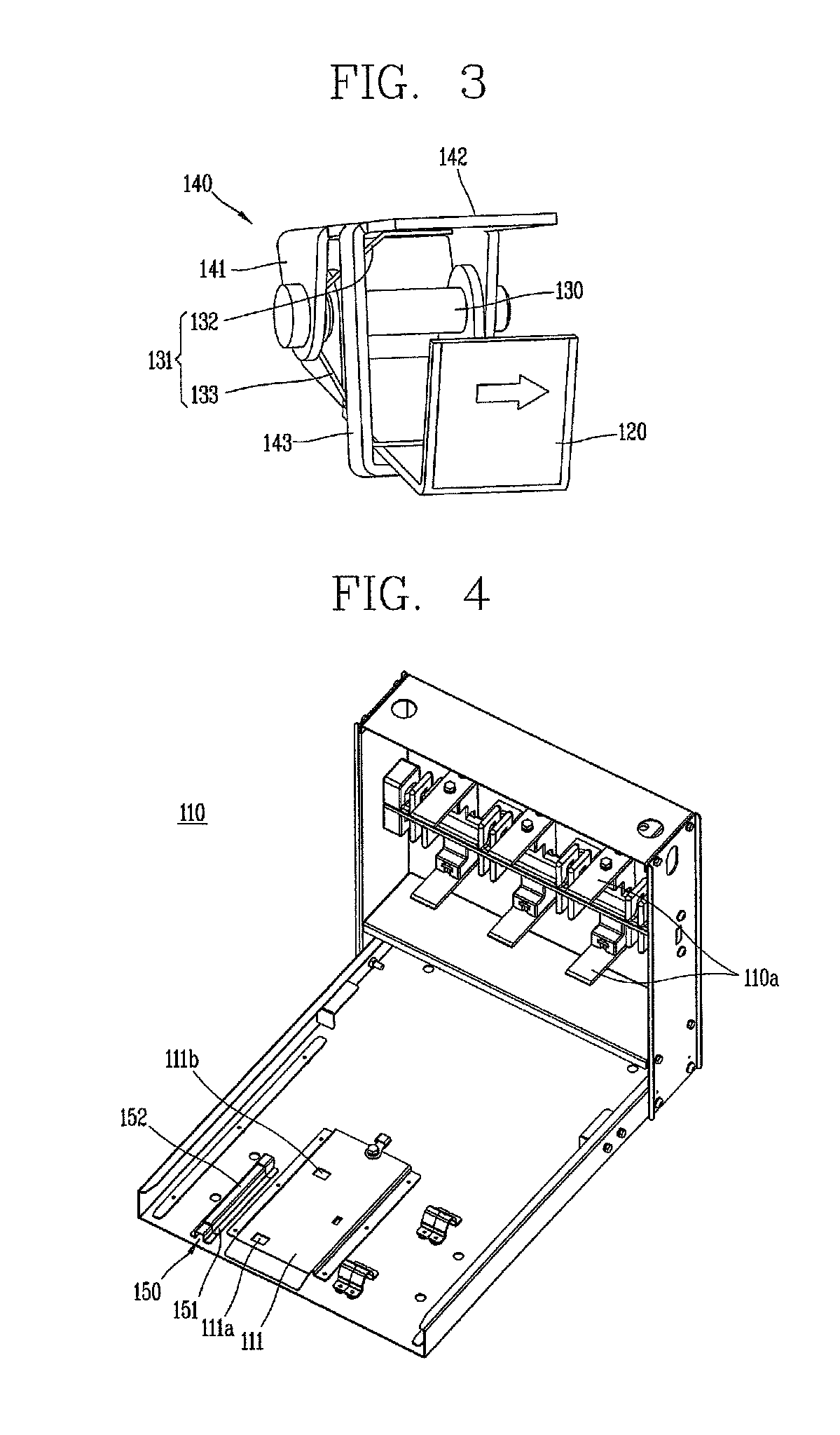
[0024]Description will be given with reference to FIGS. 1 to 3. As shown in FIGS. 1 to 3, a circuit breaker having a position indicating device in accordance with one embodiment of the present invention may include a breaker main body 100 having a switching mechanism for closing or opening an electrical circuit and contacts, the main body 100 being movable, a cradle 110 (see FIG. 4) having terminals 110a electrically connected to an electrical power source and an electrical load of an electric circuit and terminals electrically connected to the breaker main body 100, and a movable carriage 170 for supporting the breaker main body 100 and conveying the breaker main body 100 to a run position at which the breaker main body 100 is electrically connected to the terminals of the cradle and a test position at which the breaker main body 100 is separated from the terminals of the cradle and is allowed to be tested.

[0025]Referring to FIG. 1, the reference numerals 104, 105 and 106 designate...


PUM


Abstract

Disclosed is a position indicating device for a pull-out type circuit breaker used to cut off a current, the position indicating device including a position indicating plate installed at a lower surface of the circuit breaker to be rotatable up and down and having an arrow marked thereon, an indication supporter installed at a cradle and having stepped pressing surfaces for pressing up the position indicating plate, and a frame portion of a movable carriage, the frame portion having windows for externally showing a rotated state of the position indicating plate, whereby when the circuit breaker is docked with the cradle, the position indicating plate is rotated by the indication supporter so as to indicate the position of the circuit breaker through the windows, thereby allowing a fast and precise recognition of the position of the circuit breaker.

Description

CROSS-REFERENCE TO RELATED APPLICATION[0001]Pursuant to 35 U.S.C. §119(a), this application claims the benefit of earlier filing date and right of priority to Korean Application No. 10-2008-0138669, filed on Dec. 31, 2008, the contents of which is incorporated by reference herein in its entirety.BACKGROUND OF THE INVENTION[0002]1. Field of the Invention[0003]The present invention relates to a position indicating device for a circuit breaker, and particularly, to a position indicating device for a circuit breaker capable of fast and precisely indicating a position of the circuit breaker moved is within a cradle in which the circuit breaker is accommodated.[0004]2. Background of the Invention[0005]In general, a circuit breaker for high voltage is categorized into a pull-out type and a stationary type. The stationary type circuit breaker merely has a breaker main body secured at a position within an electric power distributing board. The pull-out type circuit breaker includes a movable...

Claims


Application Information

Patent Timeline
Patent Type & Authority Patents(United States)
IPC IPC(8): H01H9/20H02B11/00
CPCH02B11/10H01H71/04H01H71/0207H01H71/06H01H71/00
Inventor KIM, IN-KYUMAHN, KIL-YOUNG
Owner LG IND SYST CO LTD
Why Eureka
Try Eureka