Support foot apparatus and methods

a technology of supporting feet and supports, which is applied in the direction of electric apparatus casings/cabinets/drawers, instruments, and details of portable computers, etc., can solve the problems of support feet being prone to peeling off from the underside of the chassis

Active Publication Date: 2012-10-30
DELL PROD LP
View PDF5 Cites 6 Cited by
  • Summary
  • Abstract
  • Description
  • Claims
  • Application Information

AI Technical Summary

Benefits of technology

[0004]Disclosed herein are support foot apparatus that include a support foot structure that employs flexible flap members disposed on opposing sides of a central foot member. The opposing flexible flap members are configured for insertion into corresponding openings of a support foot location defined in an exterior surface of the chassis of an information handling system or other device or structure. Each of the flexible flap members may be provided with one or more securing apertures configured for placement over corresponding securing posts provided on an interior surface of the chassis to secure the flexible flap members of the support foot structure within the interior of the chassis at a support foot location in a manner that helps to hold the central support body against an exterior surface of the chassis and that resists peeling away of the support foot structure from the support foot location of the chassis.
[0005]In one exemplary embodiment, a support foot structure may be provided that may be advantageously assembled to a chassis in manual fashion by hand, and / or without using a fixture or heat staking process. In another exemplary embodiment, the central foot member and opposing flexible flap members may together be composed of a single piece of resilient material (e.g., rubber, urethane, thermoplastic urethane (TPU) or other rubber-like material) without the presence of any non-resilient material such as plastic or other rigid material. In such an exemplary embodiment, the disclosed support foot structure may be manufactured using a single step injection process without the complexity or cost of a multiple step injection molding process, while at the same time providing a support foot structure having good resistance to peel off from a chassis to which it has been secured.

Problems solved by technology

Such support feet are prone to peeling off from the underside of the chassis.

Method used


Image

  • Support foot apparatus and methods
  • Support foot apparatus and methods
  • Support foot apparatus and methods

Examples


Embodiment Construction

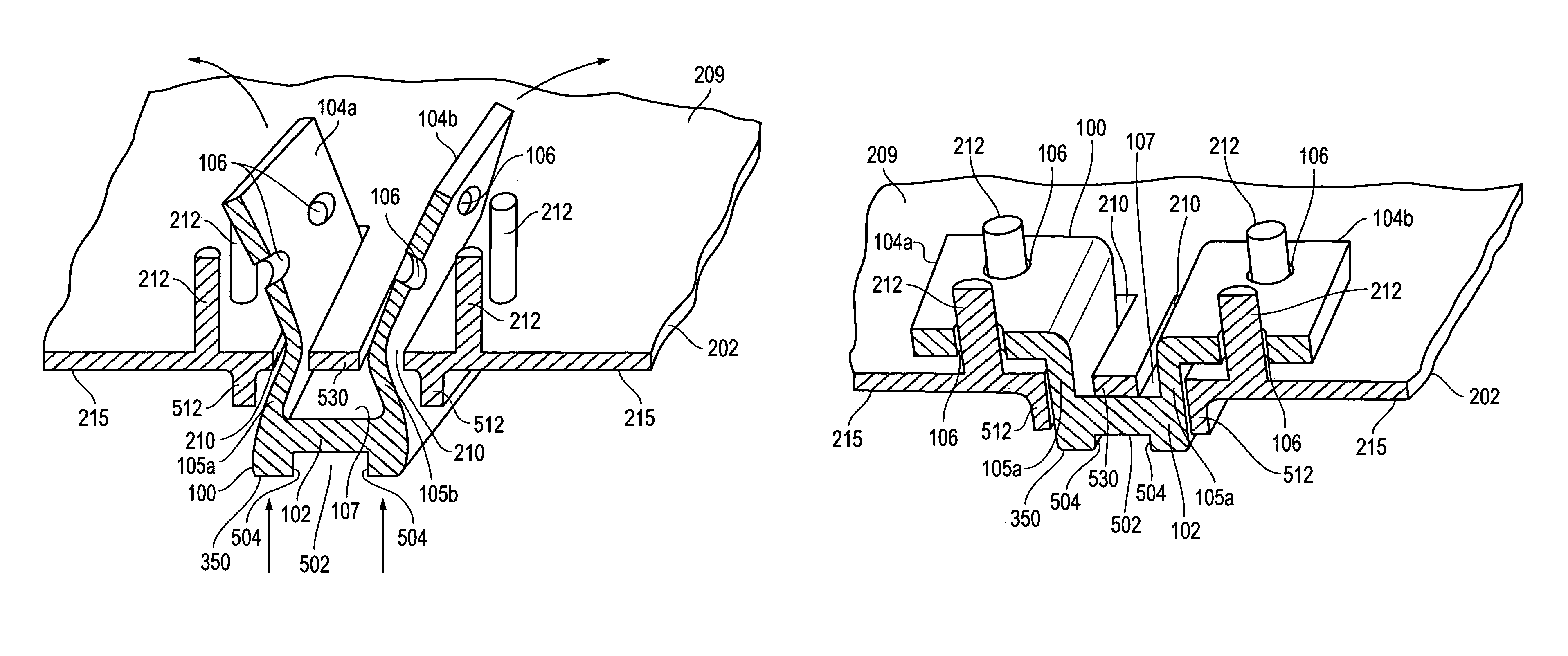
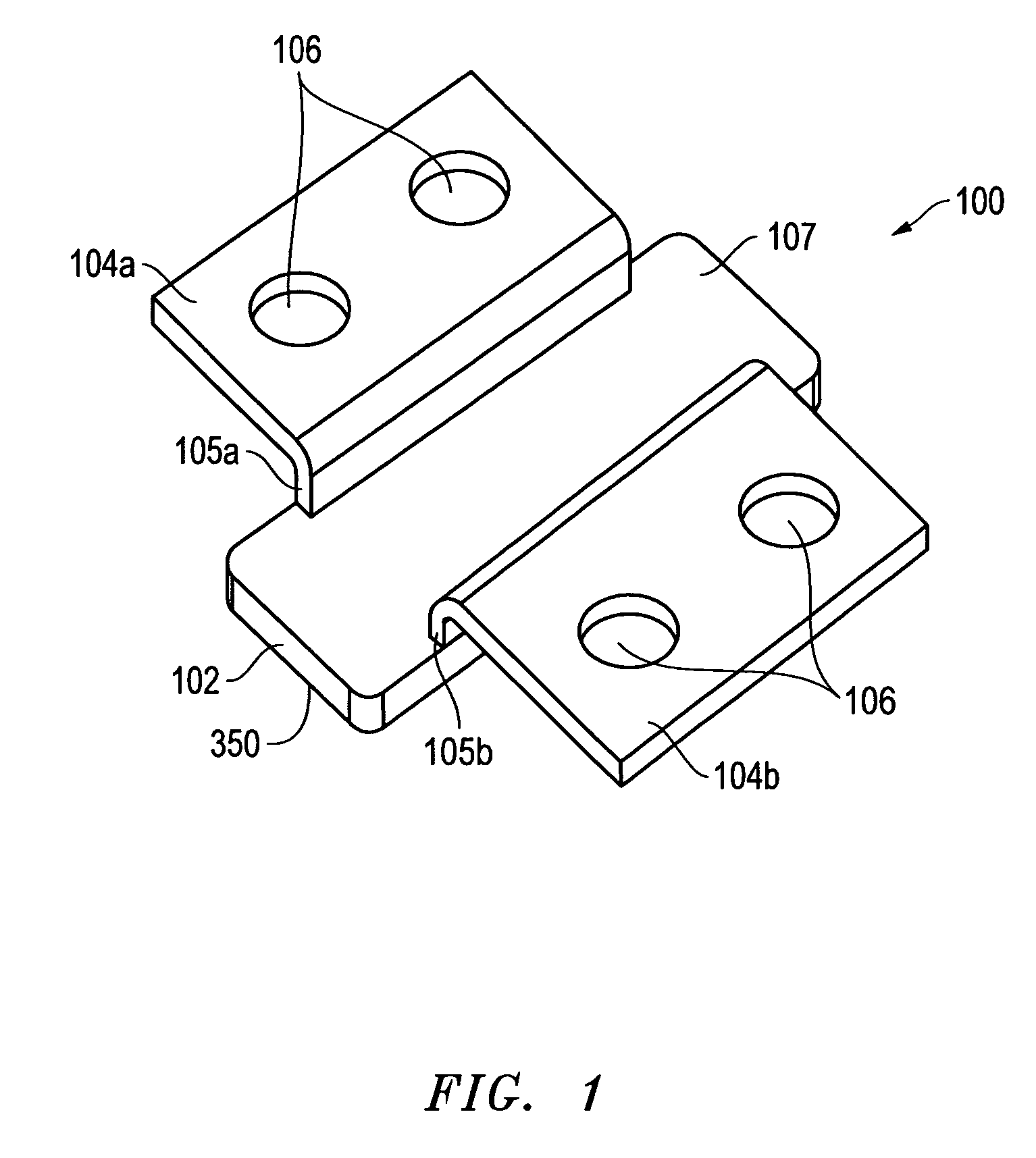
[0020]FIG. 1 illustrates a perspective view of one exemplary embodiment of a resilient support foot apparatus 100 that includes a central foot member 102 with two opposing flexible flap members 104a and 104b that in this embodiment each include a respective flexible offset section 105a or 105b that couples the respective flexible flap member 104a or 104b to central foot member 102. As further shown, support foot apparatus 100 includes two securing apertures 106 defined in each of flexible flap members 104a and 104b. Each of securing apertures 106 is configured for placement over a corresponding securing post provided on an interior surface of an information handling system chassis or other type of device chassis as will be described further herein. A chassis side surface 107 is provided for contact with an exterior side of a device chassis is provided on one side of central foot member 102, and a support side surface 350 is provided on the opposing side of central foot member 102 as...


PUM

PropertyMeasurementUnit
flexibleaaaaaaaaaa
resilientaaaaaaaaaa
adhesiveaaaaaaaaaa

Abstract

Support foot apparatus that include a support foot structure that employs flexible flap members disposed on opposing sides of a central foot member, and that are configured for insertion into corresponding openings of a support foot location defined in an exterior surface of the chassis of an information handling system or other device or structure. Each of the flexible flap members may be provided with one or more securing apertures configured for placement over corresponding securing posts provided on an interior surface of the chassis to secure the flexible flap members of the support foot apparatus within the interior of the chassis at a support foot location to hold the central support body against an exterior surface of the chassis.

Description

FIELD OF THE INVENTION[0001]This invention relates generally to support foot apparatus, and more particularly to support foot apparatus for information handling systems and other devices or structures.BACKGROUND OF THE INVENTION[0002]As the value and use of information continues to increase, individuals and businesses seek additional ways to process and store information. One option available to users is information handling systems. An information handling system generally processes, compiles, stores, and / or communicates information or data for business, personal, or other purposes thereby allowing users to take advantage of the value of the information. Because technology and information handling needs and requirements vary between different users or applications, information handling systems may also vary regarding what information is handled, how the information is handled, how much information is processed, stored, or communicated, and how quickly and efficiently the informatio...

Claims


Application Information

Patent Timeline
Patent Type & Authority Patents(United States)
IPC IPC(8): G06F1/16
CPCG06F1/1656G06F1/166Y10T29/49826
Inventor CHEN, HAO-MINGHU, CHIH-TSUNGJO, CHUNG JENHSU, JEN-CHUNHUANG, WEN-PIN
Owner DELL PROD LP
Why Eureka
Try Eureka