
Synthetic crosstie and manufacturing method for the same

A manufacturing method and technology for sleepers, which can be applied to devices, roads, tracks and other directions for coating liquid on the surface, can solve the problems of increased manufacturing cost of sleepers 11, and achieve increased bonding area, good weather resistance, and strong peeling resistance. Effect

Active Publication Date: 2007-10-03
SEKISUI CHEM CO LTD
View PDF4 Cites 5 Cited by
  • Summary
  • Abstract
  • Description
  • Claims
  • Application Information

AI Technical Summary

Problems solved by technology

[0022] Therefore, there is a problem that the manufacturing cost of the sleeper 11 increases

Method used


Image

  • Synthetic crosstie and manufacturing method for the same
  • Synthetic crosstie and manufacturing method for the same
  • Synthetic crosstie and manufacturing method for the same

Examples


Embodiment Construction

[0051] Next, a composite sleeper and a method of manufacturing the composite sleeper in the best mode for carrying out the present invention will be described with reference to FIGS. 1 to 6 . In addition, the same code|symbol is used and the same code|symbol is used about the part which is the same as or equivalent to the said previous example.

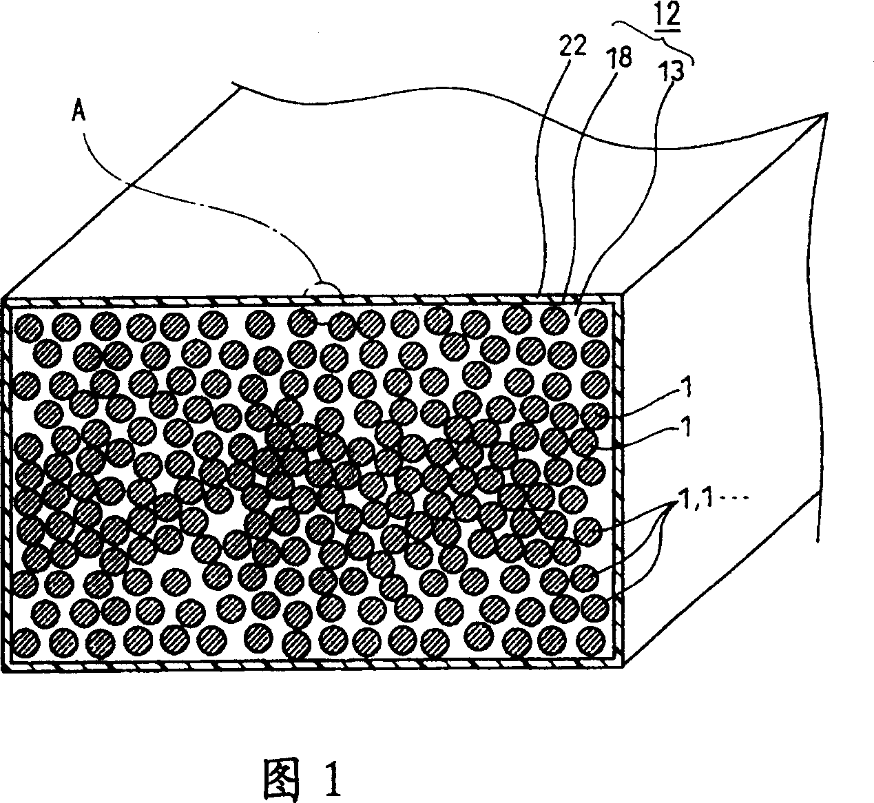
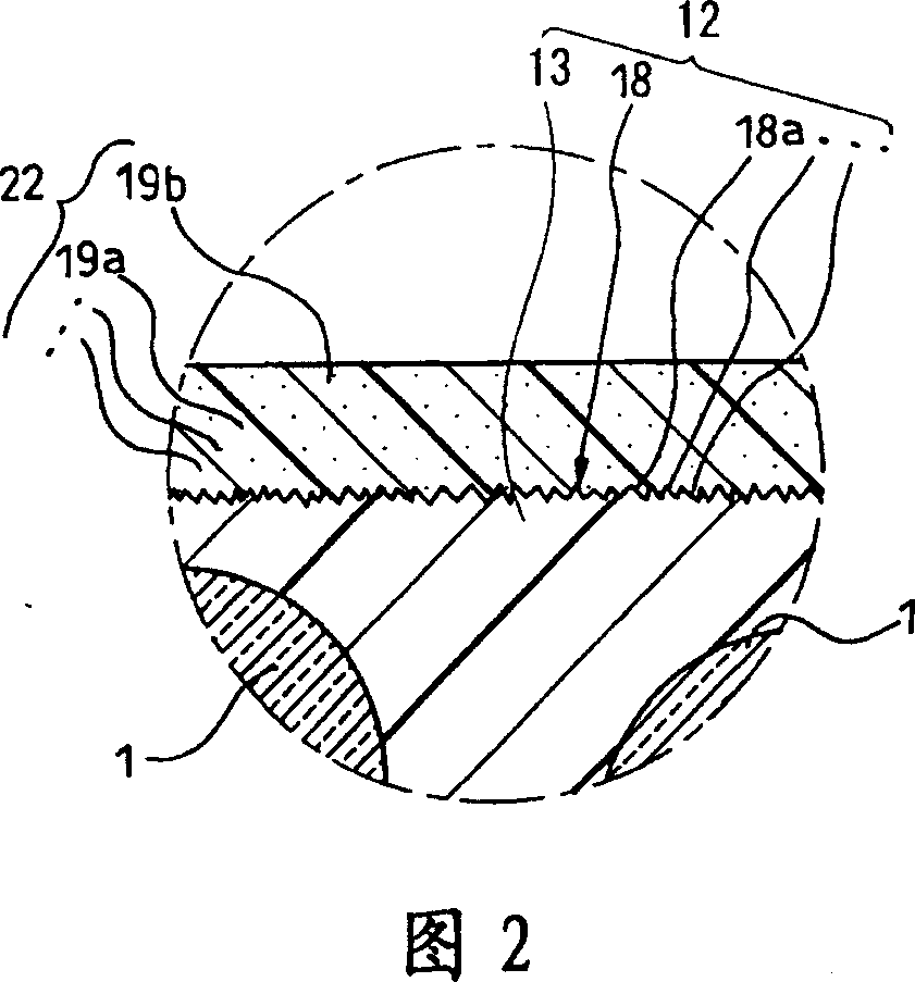
[0052] As shown in Fig. 1 and Fig. 2, the synthetic sleeper in Example 1 of this embodiment includes: a composite sleeper formed by a foam base material 13 and a plurality of long glass fibers 1 ... arranged in the foam base material 13. The sleeper body 12, and the flame retardant layer 22. In addition, the synthetic sleeper in this embodiment also includes an abrasive layer 18 disposed on the surface of the synthetic sleeper body 12 , and the flame retardant layer 22 is disposed on the surface of the abrasive layer 18 .

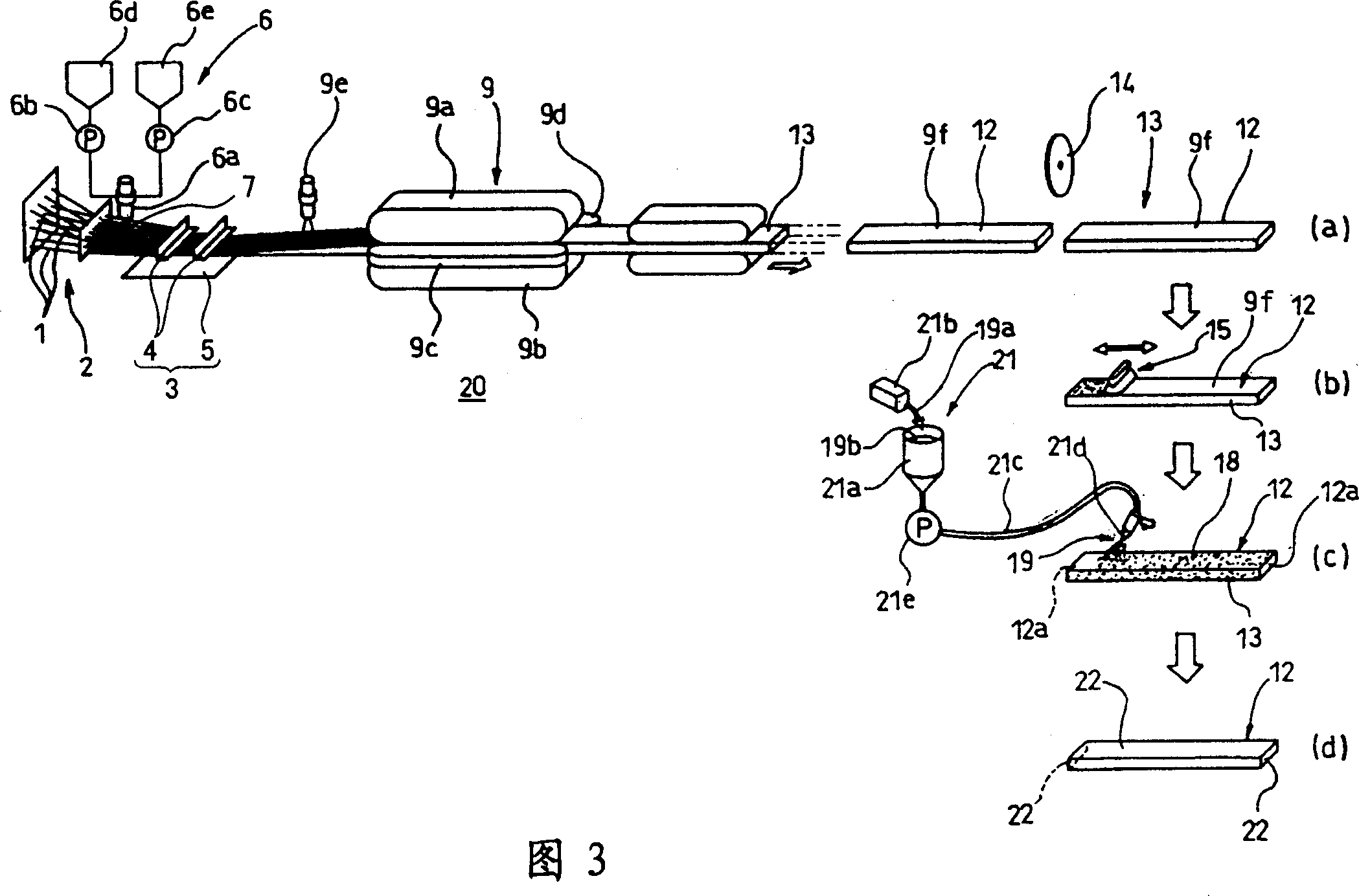
[0053] Hereinafter, the manufacturing process of the synthetic sleeper in this embodiment is demonstrated. In ...


PUM

PropertyMeasurementUnit
Viscosityaaaaaaaaaa

Abstract

The present invention provides a synthetic crosstie having excellent fire resistance and a method manufacturing synthetic crosstie. The synthetic crosstie comprises synthetic crosstie body (12), a fire resistance layer (22) formed on its surface. Sand paper (15) with roughness concentration less than or equal to #120 is used for grinding parting agent (9f) attached on the surface of the syntheticcrosstie, and a part surface (13a) of the frothing parent material (13). In the grinding layer (18) formed by grinding, innumerable unevennesses (18a) are formed corresponding to the roughness concentration of the sand paper. And, on the surface side of the grinding layer (18), the fire resistance layer (22) is formed by using the spray gun (21d) coat urethane resin dope appended with inorganic filling material.

Description

technical field [0001] The present invention relates to a synthetic sleeper and a method for manufacturing the synthetic sleeper which are mainly used for iron wheel-supported linear engine traction trains and the like, and in particular have excellent flame retardancy. Background technique [0002] As a method of manufacturing crossties conventionally used for railways, a draw-out forming machine 10 as shown in FIG. 7 is known (for example, refer to Japanese Patent Laid-Open No. 2001-252938, etc.). In the drawing-out molding machine described above, a plurality of long glass fibers 1... are drawn out in a row from the long glass fiber supply part 2 at predetermined intervals, and advance in one direction. [0003] The above-mentioned plurality of long glass fibers 1 ... are inserted between the rubbing plate 4 and the impregnating plate 5 provided in the urethane resin liquid impregnating part 3 while advancing. [0004] Wherein, the above-mentioned rubbing plate 4 can mov...

Claims


Application Information

Patent Timeline
IPC IPC(8): E01B3/44B29C44/00B29B11/16B05D5/00
Inventor 石岛勇治中尾喜浩
Owner SEKISUI CHEM CO LTD
Learn More