
Method for dynamic aperture determination for three-dimensional surface-related multiple elimination

a three-dimensional surface and multiple elimination technology, applied in the field of geophysical prospecting, can solve the problems of differences in acoustic impedance at the interface, too large aperture, and too small apertur

Active Publication Date: 2012-10-30
PGS GEOPHYSICAL AS
View PDF12 Cites 5 Cited by
  • Summary
  • Abstract
  • Description
  • Claims
  • Application Information

AI Technical Summary

Problems solved by technology

Such seismic reflectors typically are interfaces between subterranean formations having different elastic properties, specifically sound wave velocity and rock density, which lead to differences in acoustic impedance at the interfaces.
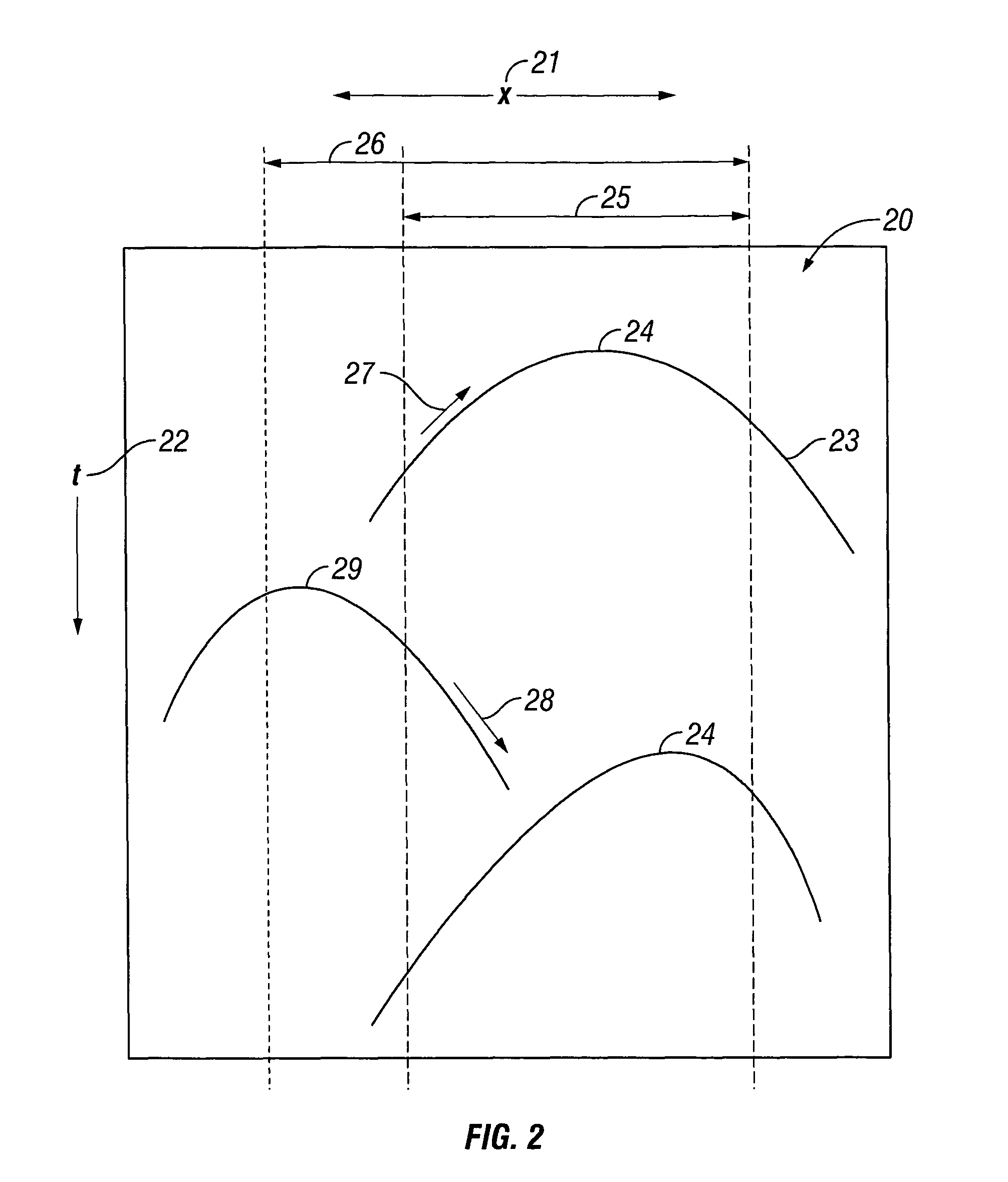
Hence, a simple choice of aperture for multiple contribution gathers will inevitably be a trade-off between cost and accuracy.
For some multiple contribution gathers, the aperture will be too large and for others it will be too small.

Method used


Image

  • Method for dynamic aperture determination for three-dimensional surface-related multiple elimination
  • Method for dynamic aperture determination for three-dimensional surface-related multiple elimination
  • Method for dynamic aperture determination for three-dimensional surface-related multiple elimination

Examples


Embodiment Construction

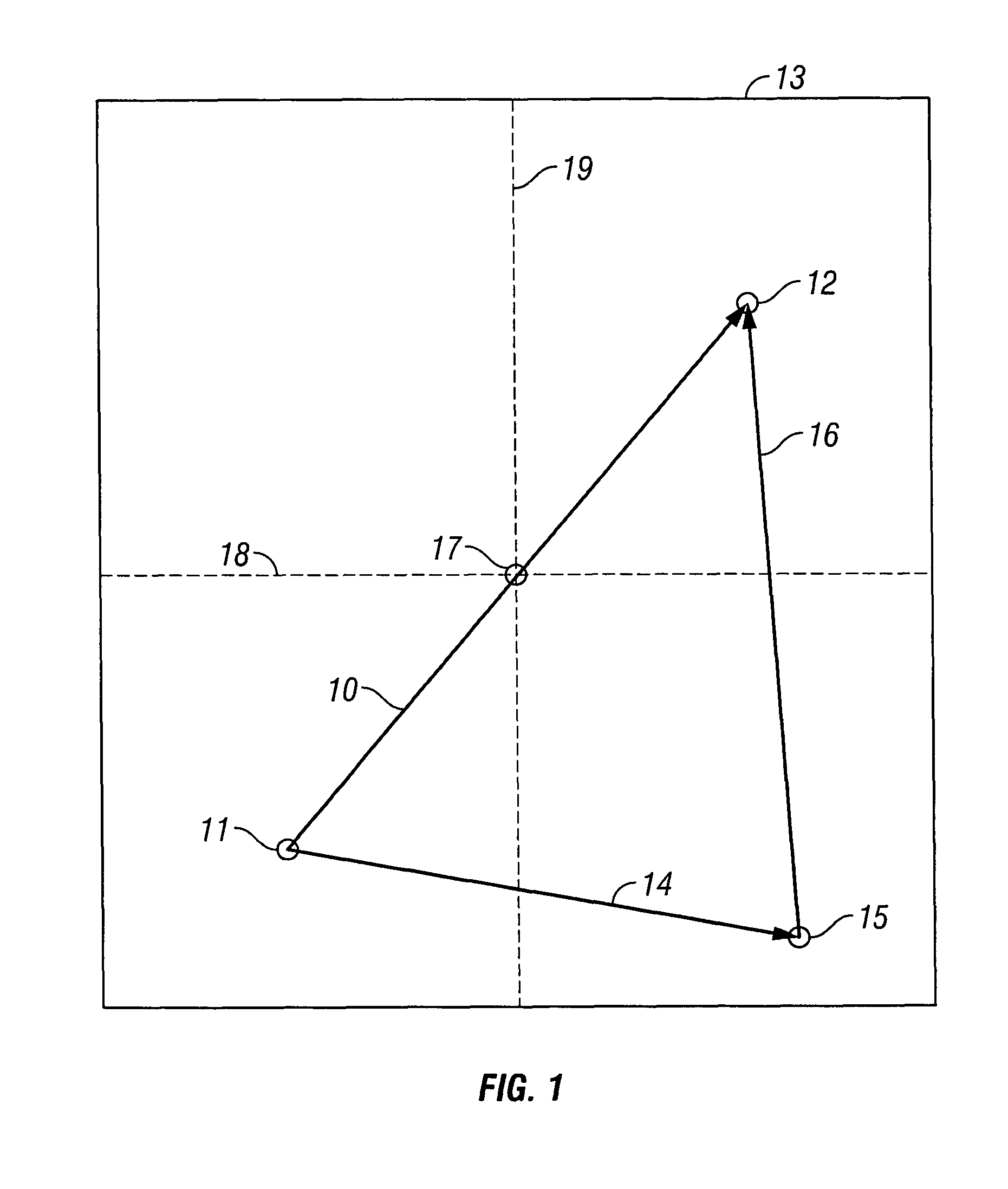
[0025]The invention is a method for transforming seismic data into noise-attenuated data, using dynamic aperture determination for a multiple contribution gather. The invention can be used in a 3D predict-and-subtract process to attenuate surface related multiples in seismic data. The location at which the multiples are to be predicted and subtracted is defined by a source-receiver trace. FIG. 1 is a schematic diagram of construction of a multiple contribution gather for a source-receiver trace, as in the method of the invention. The source-receiver trace 10 is determined by a combination of a specific source location 11 and a specific receiver location 12. The process of predicting the surface related multiples from seismic data for this source-receiver trace 10 comprises convolving pairs of traces and then accumulating the convolution results over a surface area 13. The first trace 14 in each pair of convolved traces has the same specific source location 11 as the source-receiver ...


PUM


Abstract

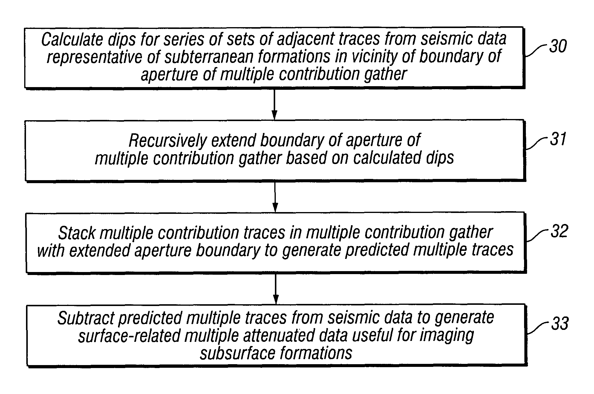
Dips are calculated for a series of sets of adjacent multiple contribution traces, from seismic data representative of subsurface formations, in the vicinity of a boundary of an aperture of a multiple contribution gather, the seismic data acquired by deploying a plurality of seismic sensors proximate an area of the earth's subsurface to be evaluated, the seismic sensors generating at least one of an electrical and optical signal in response to seismic energy. The boundary of the aperture of the multiple contribution gather is recursively extended, based on the calculated dips. Multiple contribution traces in the multiple contribution gather with the extended aperture boundary are stacked to generate predicted multiple traces. The predicted multiple traces are subtracted from the seismic data to generate surface-related multiple attenuated data useful for imaging the subsurface formations.

Description

CROSS-REFERENCES TO RELATED APPLICATIONS[0001]Not ApplicableFEDERALLY SPONSORED RESEARCH OR DEVELOPMENT[0002]Not ApplicableSEQUENCE LISTING, TABLE, OR COMPUTER LISTING[0003]Not ApplicableBACKGROUND OF THE INVENTION[0004]1. Field of the Invention[0005]This invention relates generally to the field of geophysical prospecting. More particularly, the invention relates to the field of surface related multiple elimination in marine seismic surveys.[0006]2. Description of the Related Art[0007]In the oil and gas industry, geophysical prospecting is commonly used to aid in the search for and evaluation of subterranean formations. Geophysical prospecting techniques yield knowledge of the subsurface structure of the earth, which is useful for finding and extracting valuable mineral resources, particularly hydrocarbon deposits such as oil and natural gas. A well-known technique of geophysical prospecting is a seismic survey.[0008]The resulting seismic data obtained in performing a seismic survey...

Claims


Application Information

Patent Timeline
Patent Type & Authority Patents(United States)
IPC IPC(8): G01V1/00
CPCG01V1/364G01V2210/56
Inventor HEGGE, ROBERTUS F.VAN BORSELEN, ROALD G.
Owner PGS GEOPHYSICAL AS
Learn More