Dynamic aperture and projection device having same

a projection device and dynamic aperture technology, applied in the field of aperture and projection device, can solve the problems of limited bit depth, inability to reproduce low-level signals typical of most video sources, and digital micro-mirror devices (dmds) as spatial light modulators

Inactive Publication Date: 2010-07-13
HON HAI PRECISION IND CO LTD
View PDF5 Cites 4 Cited by
  • Summary
  • Abstract
  • Description
  • Claims
  • Application Information

AI Technical Summary

Benefits of technology

[0005]FIG. 4 shows an alternative proposed aperture 2. The aperture 2 includes a motor 3, a disc 4, and a stop rod 7. The disc 4 is installed to the motor 3 providing rotation of the disc 4 and defines two slots 5 shaped in an Archimedean spiral. One of the slots 5 is positioned in the light path to adjust light throughput. The other slot 5 is coupled to the stop rod 7 which can be controlled to stop the rotating disc 4 at an appropriate position to produce a desired light throughput. A shortcoming of the aperture 2 is that a narrow, thick connection portion 6 between the slots 5 can be easily broken by the stop rod 7, shortening service time of the aperture 2.

Problems solved by technology

In digital light processing (DLP) projectors, digital micro-mirror devices (DMDs) as spatial light modulators, which bit-depth is limited, cannot reproduce low-level signals typical of most video sources.

Method used


Image

  • Dynamic aperture and projection device having same
  • Dynamic aperture and projection device having same
  • Dynamic aperture and projection device having same

Examples


Embodiment Construction

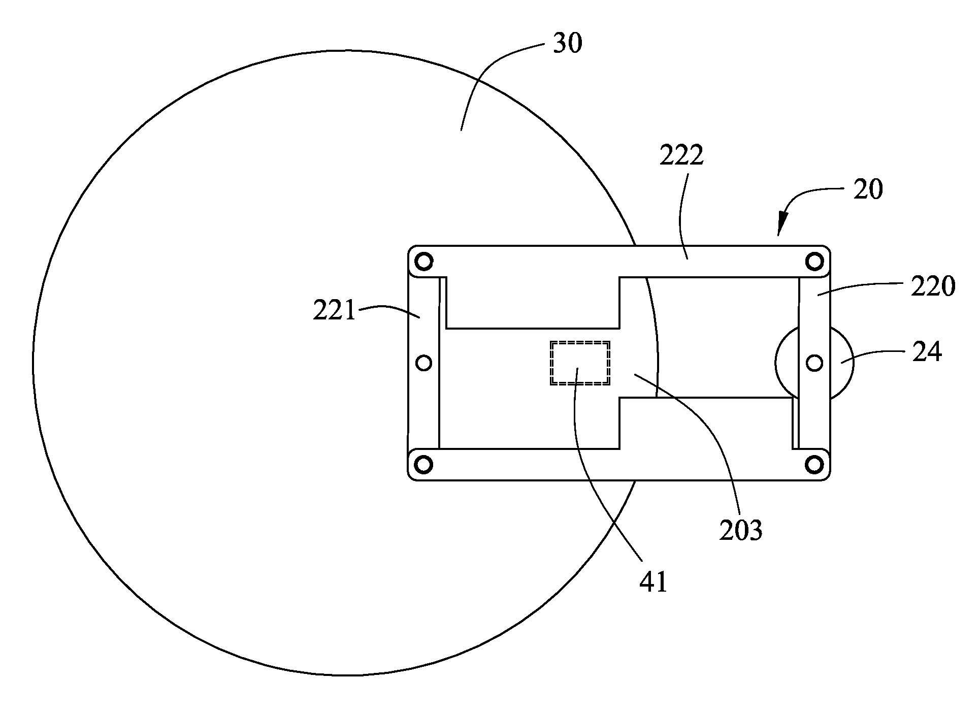
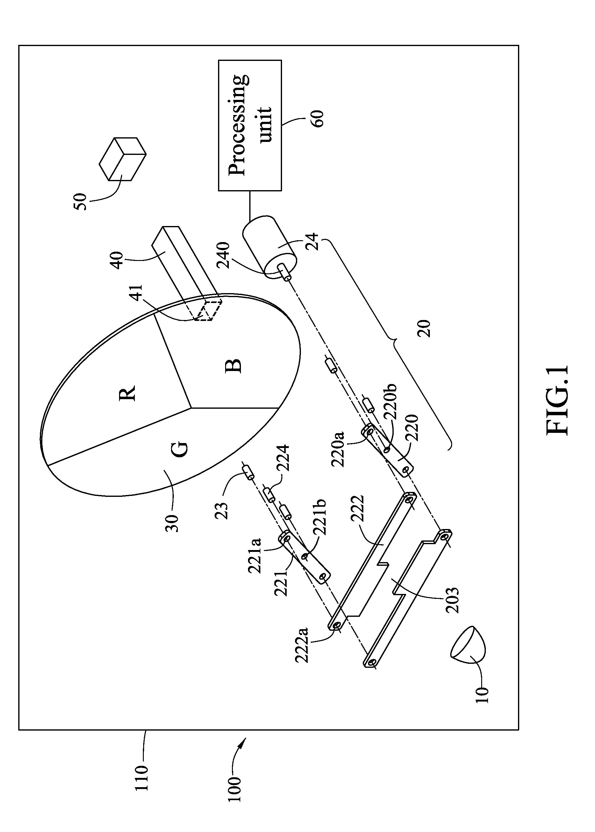
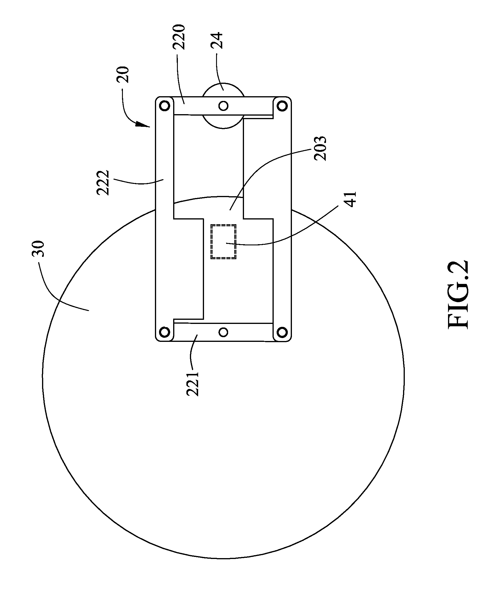
[0012]As shown in FIG. 1, a projection device 100, according to an exemplary embodiment, includes a light source 10, a dynamic aperture 20, a color wheel 30, an integrator rod 40, and a spatial light modulator 50. The projection device 100 also includes a housing 110 configured for receiving the light source 10, the dynamic aperture 20, the color wheel 30, the integrator rod 40, and the spatial light modulator 50 therein. The light source 10 is configured for generating light. The dynamic aperture 20, the color wheel 30, the integrator rod 40, and the spatial light modulator 50 are arranged along the path of the generated light. The light transmits through the dynamic aperture 20, the color wheel 30, and the integrator rod 40, and is modulated by the spatial light modulator 50 to produce an image which will be projected on a screen (not shown).

[0013]Also referring to FIGS. 2-3, the dynamic aperture 20 includes a driving member 220, a connecting member 221, two blades 222, and an ape...


PUM


Abstract

A dynamic aperture, positioned in the path of light, includes a pair of parallel blades, a connecting member, a driving member, and a motor. The projection device includes a light source configured for generating light. The connecting member is fixed to the projection device and rotatably interconnects a same side of the blades. The driving member rotatably interconnects the opposite side of the blades so that the blades, the connecting member, and the driving member constituting a variable quadrangular frame. The motor is coupled to the driving member and is configured for rotating the driving member. Rotation of the driving member and restriction of the projection device to the connection member alter dimensions of the variable quadrangular frame and accordingly adjust a gap between the blades through which the generated light passes.

Description

BACKGROUND[0001]1. Technical Field[0002]The disclosure relates to aperture and projection devices and, particularly, to a dynamic aperture and a projection device having the same.[0003]2. Description of the Related Art[0004]In digital light processing (DLP) projectors, digital micro-mirror devices (DMDs) as spatial light modulators, which bit-depth is limited, cannot reproduce low-level signals typical of most video sources. Therefore, a gain is applied to the input signal to obtain more dynamic range for the projection. However, since the input signal has been electrically amplified, it is necessary to optically reduce the brightness of the corresponding image to appropriate levels by use of an aperture in the light path of the DLP projectors. Furthermore, the aperture and gain must be dynamically determined frame-by-frame.[0005]FIG. 4 shows an alternative proposed aperture 2. The aperture 2 includes a motor 3, a disc 4, and a stop rod 7. The disc 4 is installed to the motor 3 prov...

Claims


Application Information

Patent Timeline
Patent Type & Authority Patents(United States)
IPC IPC(8): G03B21/14G03B21/22G02B26/02
CPCG02B5/005G02B26/008G02B26/02G02B7/006
Inventor CHUNG, HSIEH-TUNGYEH, WEN-PIN
Owner HON HAI PRECISION IND CO LTD
Why Eureka
Try Eureka